10 AXOS
5
Compact immunity test System
AUX (Pos. 7.) function description
1 Red warning lamp Indicates when safety circuit closed
2 Green warning lamp Indicates when safety circuit opened
3 GND 0 V
4 GND 0 V
5 Safety interlock When safety barriers installed, connection
must be done between pin 5 and pin 4 to close
the circle (safety instruments), however, bridge
between pin 4 and pin 5 exist as delivery
setting
6 GND 0 V
7 Start/Stop program 1 is running (Input) Start/Stop automatic for starting a predefined
program in the “Setup” menu “start file (Figure
5-3)”, signal for instance external device, PLC
signal
8 GND 0 V
9 Trigger Input Input for external trigger to start for instance
through an external signal a generator
10 GND 0 V
11 EUT Fail (Input) External condition (e.g. device or PLC signal),
the position becomes 1 and causes an action
(Ignore, Alarm, Test Stop or test stop & line off)
12 GND 0 V
13 0-10V Analogue output Reserved and used for further application
14 GND 0 V
15 Trigger output When Burst, Surge or Voltage dips package in
use, signal becomes 0, after the applied
package has finished the signal becomes
1(negation); used for indication of signal on
oscilloscope
16 GND 0 V
17 Spare (Reserve) Not in use
18 GND 0 V
Table 5-3: AUX function description
5.3
SETUP menu
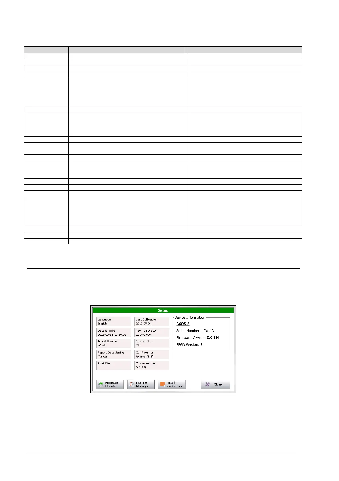
The Figure 5-3 shows the “Setup” menu after selecting this button in the starting field. Every button is explained in the
Table 5-4.
Figure 5-3: Setup menu
In the right upper corner the current software version, serial number can be seen. The FPGA indicates the hardware of
the chip version.