AXOS
5
Compact immunity test System 41
14.4
Table of figure
Figure 1-1: Safety sign ..................................................................................................................................................... 1
Figure 2-1: Start display ................................................................................................................................................... 2
Figure 4-1: Transformer connection ................................................................................................................................. 7
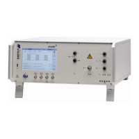
Figure 5-1: AXOS
5
Front view .......................................................................................................................................... 8
Figure 5-2: AXOS
5
rear view ............................................................................................................................................ 9
Figure 5-3: Setup menu.................................................................................................................................................. 10
Figure 5-4: Save and load option of data ....................................................................................................................... 11
Figure 5-5: File selection Internal/Standard ................................................................................................................... 12
Figure 6-1: Open circuit voltage (OCV) [1] ..................................................................................................................... 13
Figure 6-2: Short circuit current (SCC) [1] ...................................................................................................................... 14
Figure 6-3: Surge Standard mode.................................................................................................................................. 14
Figure 6-4: Surge pre-compliance mode........................................................................................................................ 15
Figure 6-5: Surge peak voltage ...................................................................................................................................... 15
Figure 6-6: Surge Pre-compliance mode charging......................................................................................................... 16
Figure 6-7: Surge properties .......................................................................................................................................... 16
Figure 6-8: SURGE transition mode............................................................................................................................... 17
Figure 7-1: Magnetic field Pre-compliance mode ........................................................................................................... 19
Figure 7-2: Magnetic field Standard mode ..................................................................................................................... 19
Figure 7-3: Magnetic field charging ................................................................................................................................ 20
Figure 7-4: Coil Antenna factor ...................................................................................................................................... 20
Figure 7-5: Magnetic field transition ............................................................................................................................... 21
Figure 8-1: EFT/BURST Standard mode........................................................................................................................ 22
Figure 8-2: EFT/BURST peak voltage configuration ...................................................................................................... 22
Figure 8-3: EFT / BURST pre-compliance mode............................................................................................................ 23
Figure 8-4: Burst pre-compliance mode charging .......................................................................................................... 23
Figure 8-5: BURST properties ........................................................................................................................................ 24
Figure 8-6: BURST Transition ........................................................................................................................................ 24
Figure 8-7: BURST mode Trigger normal....................................................................................................................... 25
Figure 9-1: Voltage interrupts electrical installation........................................................................................................ 26
Figure 9-2: DIP 116 Transformer connected .................................................................................................................. 26
Figure 9-3: Voltage Dips Standard mode ....................................................................................................................... 27
Figure 9-4: Voltage Dips pre-compliance mode (External transformer) ......................................................................... 27
Figure 9-5: Transformer DIP 116.................................................................................................................................... 28
Figure 9-6: External transformer..................................................................................................................................... 29
Figure 9-7: Voltage Dips Transition................................................................................................................................ 30
Figure 11-1: License manager ....................................................................................................................................... 33
Figure 12-1: PDP 8000................................................................................................................................................... 34
Figure 12-2: Current transformer.................................................................................................................................... 34
Figure 12-3: EFT Verification Kit .................................................................................................................................... 35
Figure 12-4: Burst verification adapter ........................................................................................................................... 35