23
Capture Jet
®
Water Wash
Operation & Maintenance & Service Manual
CJOWWM/012009/rev1/EN
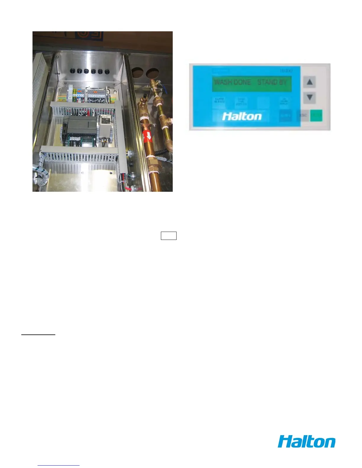
CONTROL PANEL - INPUT - OUTPUT DESCRIPTION
Fire Switch – Normally Open contract of re relay in any re suppression system (for example Ansul) switch connected to
terminals 8 and 10
• When switch is closed, gives signal to control panel and noties that system is on re.
• Alarm lamp(red color)lit and display shows FIRE
• Exhaust and Makeup fans may be shut off (depending on internal programming)
• This particular alarm remains active even when unit is in Off position
Remote AUTO/WASH/RUN switch -
Used to remotely turn the system in RUN and WASH
• If remote control for the panel is needed, this switch is on AUTO position
• This enables panel to be controlled from external or internal time clock, BMS or similar
systems.
OUTPUTS
Exhaust Fan – terminals 1 and N.
AC voltage to energize exhaust fan starter,120 VAC.
Makeup Fan – terminals 2 and N.
AC voltage to energize makeup fan starter,120 VAC.
Cold Water Solenoid - terminal Q0.7 and N
Hot Water Solenoid - terminal Q1.0 and N
Alarm signal output – Terminal numbers to be assigned.
Dry contacts which close/open on certain alarms can be provided to send signal to remote
monitoring system.



 To Next Page