Do you have a question about the Halton M.A.R.V.E.L. and is the answer not in the manual?
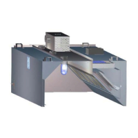
Overview of the demand control ventilation system, its purpose, and key partnerships.
Highlights the four unique components that distinguish the M.A.R.V.E.L. system.
Details the MC8 controller's role as the system's core processing unit and its inputs/outputs.
Explains the function of the pressure transducer in measuring and controlling airflow.
Describes the temperature sensor's use in detecting cooking activity and controlling airflow.
Discusses the flexibility of the M.A.R.V.E.L. system for single or multiple hood applications.
Details the infrared sensors, their mounting, function for heat signature detection, and connection.
Explains the function and connection of the duct temperature sensor for monitoring exhaust air.
Describes the pressure sensor's role in real-time airflow calculation within the hood.
Explains the function and control mechanism of the automatic balancing damper for airflow adjustment.
Covers alarm lights, buzzers, and the conditions that trigger them.
Details the two modes of the override push button for temporary manual control.
Describes the VFD's function in controlling fan speed and its installation considerations.
Details the mounting and connection interfaces of the control panel located on each hood.
Explains the purpose and connections of the central control panel for multi-unit systems.
Introduces the concept of operational sequences for controlling exhaust hood performance.
Details the various modes including Startup, Shutdown, Idle, Active, and Override operations.
Describes the system's actions and safety protocols during a fire detection event.
Explains the conditions under which the system automatically shuts down.
Details how exhaust airflow is monitored and used to manage building pressurization.
Covers system monitoring for abnormal conditions and the methods of alarm indication.
Provides step-by-step instructions for the physical installation of the central control panel.
Lists the required electrical and communication connections for the central control panel.
Outlines the steps for connecting the Variable Frequency Drive to the system.
Details the procedure for linking individual hood control panels to the central unit.
Instructions to verify the integrity of the pressure transducer tubing.
Provides a detailed procedure for calibrating and aligning the IRIS™ sensors.
Describes the process of calibrating exhaust air flows using T.A.B. ports.
Explains the steps for calibrating the complete M.A.R.V.E.L. system using the software.
Specific instructions for performing system calibration using the Konsole™ software interface.
Describes the process of monitoring space, IR, and exhaust temperatures for operational control.
Explains the decision-making process based on exhaust and IR sensor temperature thresholds.
Defines the system's states and transitions based on detected cooking activity.
Details how the override button temporarily increases exhaust airflow for specific durations.
Provides general advice for effective preventive maintenance and safety practices.
Step-by-step instructions for cleaning the IRIS™ sensor optics.
Procedure for aligning the IRIS™ sensor, recommended quarterly or as needed.
Detailed instructions for removing and installing the IRIS™ sensor assembly.
Step-by-step guide for removing and replacing the temperature sensor probe.
Instructions for removing and replacing the automatic balancing damper actuator.
Procedure for removing and replacing the pressure transducer unit.
Outlines the options for permanent and temporary Ethernet connections for system monitoring.
Information on the software used for commissioning, monitoring, and troubleshooting the system.
Explanation of key data fields and recommended values within the Konsole™ software.
Provides contact information for Halton Company in the United States.
Provides contact information for Halton Indoor Climate Systems in Canada.
Details the duration and scope of the manufacturer's limited warranty for products.
Outlines conditions, damages, and alterations not covered by the warranty.
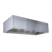
| Application | Commercial kitchens |
|---|---|
| Material | Stainless steel |
| Noise Level | Low |
| Energy Efficiency | High |
| Filter Class | Grease filters |
| Installation | Ceiling mounted |
| Technology | Demand-controlled ventilation |
| Control System | Automated with sensors |
| Airflow Capacity | Variable, based on demand |