7
M.A.R.V.E.L. Installation Operation & Maintenance Manual
MARVELIO&M/022009/rev1/EN
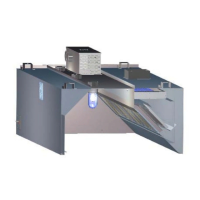
Equipment Description Power + Connection Details
PT
Hood plenum
pressure
sensor
Used to calculate air fl ow in a hood in real time.• Power source: 24 V DC power
supply located in a control panel.
Connection: at terminal block
located behind a cover on the
Capture Jet
®
plenum.
ABD
Automatic
balancing
damper
NOTE:
For multiple hood installations with a single
exhaust fan only
Adjusts air fl ow with motorized balancing •
dampers attached to a collar at each hood.
Damper controlled by a 0-10 V DC position •
reference signal generated by a controller.
Upon power failure, the automatic balancing •
damper fully opens.
Power source: 24 V AC
transformer located in the control
panel.
Connection: at terminal block
located behind a cover on the
Capture Jet® plenum
Alarm light and
audible alarm/
buzzer
Activated when any alarm condition is detected. •
Common alarm conditions include: fi lter missing, •
fi lter clogged, fi re suppression system activated,
duct temperature dangerously high, sensor
failed, or VFD is in fault.
NOTE:
To easily diagnose the alarm, use the remote
Konsole™ Diagnostic Software.
Override push
button
Used to override pre programmed operation.•
Two modes:•
Press and hold for 1 second to accelerate 1.
the exhaust rate to 100% of the design air
fl ow for a pre programmed period of time
(default 5 minutes.)
Press and hold for 3 seconds to accelerate 2.
the exhaust rate to 100% of the design air
fl ow for a pre programmed period of time
(default 1 hour.) Starts the hood if it has
been overridden by a schedule or an ‘off’
state.
Connection: at terminal block
located behind a cover on the
Capture Jet
®
plenum.
Room
temperature
sensor
Mounted on a kitchen wall close to a thermostat.• Connections: to the control panel
with 2 wires
VFD
Variable
Frequency
Drive
Controls the speed of a three-phase fan motor •
by changing the frequency of the current to the
motor.
For smaller fans, mount the VFD in a cabinet •
attached to a hood.
For larger exhaust fan units, attach the VFDs to a •
fan unit or cabinet or mount remotely.
Power source: varies as per fan’s
voltage requirement
Connection: at terminal block in
VFD control panel to main control
panel
Speed reference: 0-10 VDC