6
M.A.R.V.E.L. Installation Operation & Maintenance Manual
MARVELIO&M/022009/rev1/EN
FLOW
AIR
TS
FUSIBLE LINK
IR1
IR2 IR3
Exhaust Fan
PT
TS
FUSIBLE LINK
IR1
IR2 IR3
PT
ABD
ABD
CONTROLLER
ST
VFD
CP
CONTROLLER
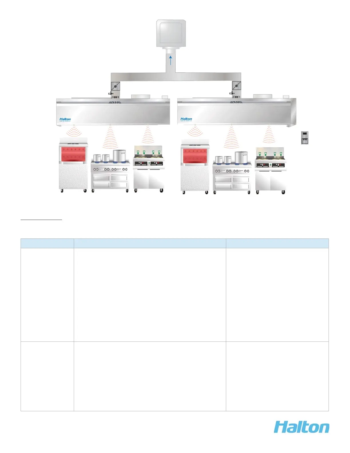
Figure 2: Multiple Hood M.A.R.V.E.L. Installation
Components
NOTE: Refer to Figure 1+2
Equipment Description Power + Connection Details
IR1, IR2, IR3|
Infrared
radiation sensor
(IRIS™)
Mount 1 to 4 IRIS™ sensors per hood depending •
on the length of the hood.
Calculates an index which averages the •
temperature radiation over the sensor’s fi eld-of-
view.
Used to detect when one or more pieces of •
cooking equipment are turned on and it is
necessary to start the hood fan in idle mode.
Used to measure a rapid change in temperature •
of cooking surfaces (for example, cooking
activities) and adjust the air fl ow in the hood to
the required level.
Power source: 5 volt DC power
supply located in a control panel.
Connection: at terminal block
located behind a cover on the
Capture Jet
®
plenum.
TS
Duct
temperature
sensor
Measures the temperature of the exhaust air.•
Located in the hood collar.•
Used (in conjunction with the IR Index) to detect •
the event of cooking equipment start-up. Duct
temperature is often a better indicator of start-up
in the case of certain types of equipment such
as a gas fryer.
Used to activate the early fi re detection alarm, •
activated before the fi re system is triggered.
Connection: at terminal block
located behind a cover on the
Capture Jet
®
plenum.