14
M.A.R.V.E.L. Installation Operation & Maintenance Manual
MARVELIO&M/022009/rev1/EN
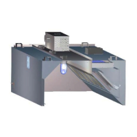
6. Calibrate and align IRIS™ Sensor
NOTE:
The IRIS™ Sensor is calibrated after installation in the hoods.
The sensor is tested using a ‘black body’ (does not refl ect IR light) such as a sheet metal with a diameter
of at least 16” (aluminum) and painted black). Always store this calibration tool away from direct sunlight
and where the space temperature can be measured.
The IRIS™ sensor calibration is done in the factory. It has to be done in the fi eld only when the sensor is
replaced.
To calibrate the IRIS™ Sensor, follow these steps:
1. Install the IR sensors in the hood and terminate them.
2. Direct the IR sensors vertically down.
3. Start the control system and launch the Konsole™ software.
4. Bring the calibration tool closer to the sensor (approximately 3-5” from the sensor).
The distance between the sensor and the tool should guarantee the fi eld of view of
the sensor will be completely within the black body surface.
5. Register the space temperature t (in ˚F).
6. Register the IR _Temp reading T (in ˚F).
7. Calculate the calibration offset: Calib_Offset = t – T
8. Assign this value in the Konsole™ screen to the appropriate parameter.
9. Check the IR_Temp reading. The reading should be equal to the hood’s space
temperature reading.
10. Align the IRIS™ sensor(s). See IRIS™ Sensor Alignment (Quarterly or as required),
page 18 for details.
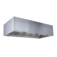
9. Calibrate the Capture Jet
®
exhaust air fl ows
Calibrate the Capture Jet
®
exhaust air fl ows using the T.A.B.™ (Testing and Balancing Ports).
To determine the correct T.A.B. port reading for the exhaust hoods, follow these steps:
Ensure that the equipment is operating to create a thermal plume prior to the air 1.
balancer.
Determine the correct T.A.B. port reading (IWC) based on the Capture Jet2.
®
hood
model.
Capture Jet T.A.B. Port Readings
Hood Model Design T.A.B. (inches WC)
KVE/KVC 0.25
KVW 0.25
KVR 0.25
KVL 0.28
“Example Only”