Technical Manual VERSION 2.0 -10-18-2018
56
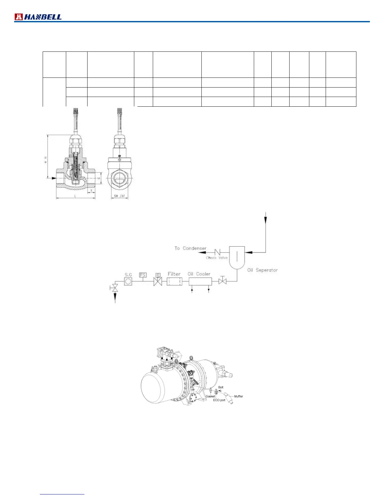
p. Oil flow switch
Oil flow switch operates with external oil separator to prevent oil deficient compressor. Specification and installation
of oil flow switch are shown as below:
G Type
bar
Qmax. Recom.
l/min
switch value l/min
fixed switch
L
mm
H
mm
SW
mm
X
mm
Weight kg
bronze
G 1/2
FF015GR012 200
20 0.412 68 79 29 13
0.6
G 3/4
FF020GR025 25 40 0.625 73 79 32 11
0.7
G 1 FF025GR040 25 60 1.540 87 90 41 14
1
Figure 45 Outline of oil flow switch
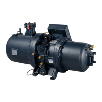
q. Economizer connection muffler
When economizer is used, it is recommended to install a muffler and check valve before middlepressure returned
gas port in compression chamber to effectively mitigate pulsation noise in middle pressure as shown in the drawing
below:
Figure 47 Installation of ECO muffler
r. Mounting pad
To avoid extra vibration and noise resulted from direct contact between compressor footings and the base on which
compressor is mounted, it is recommended to add mounting pads in between as the drawing below shown.
From compressor
To compressor
oil return port
Figure 46 Installation of oil flow switch
(1)Tolerance: ±0.3l/min
(2)Media temperature: max 110 ℃
(3)Average pressure loss: 0.4 bar at Qmax
(4)Hysteresis:depending on switch value minimum 0.4 l/min
Note: Switch value is indicated for horizontally decreasing flow