Technical Manual VERSION 2.0 -10-18-2018
57
E
A
B
D
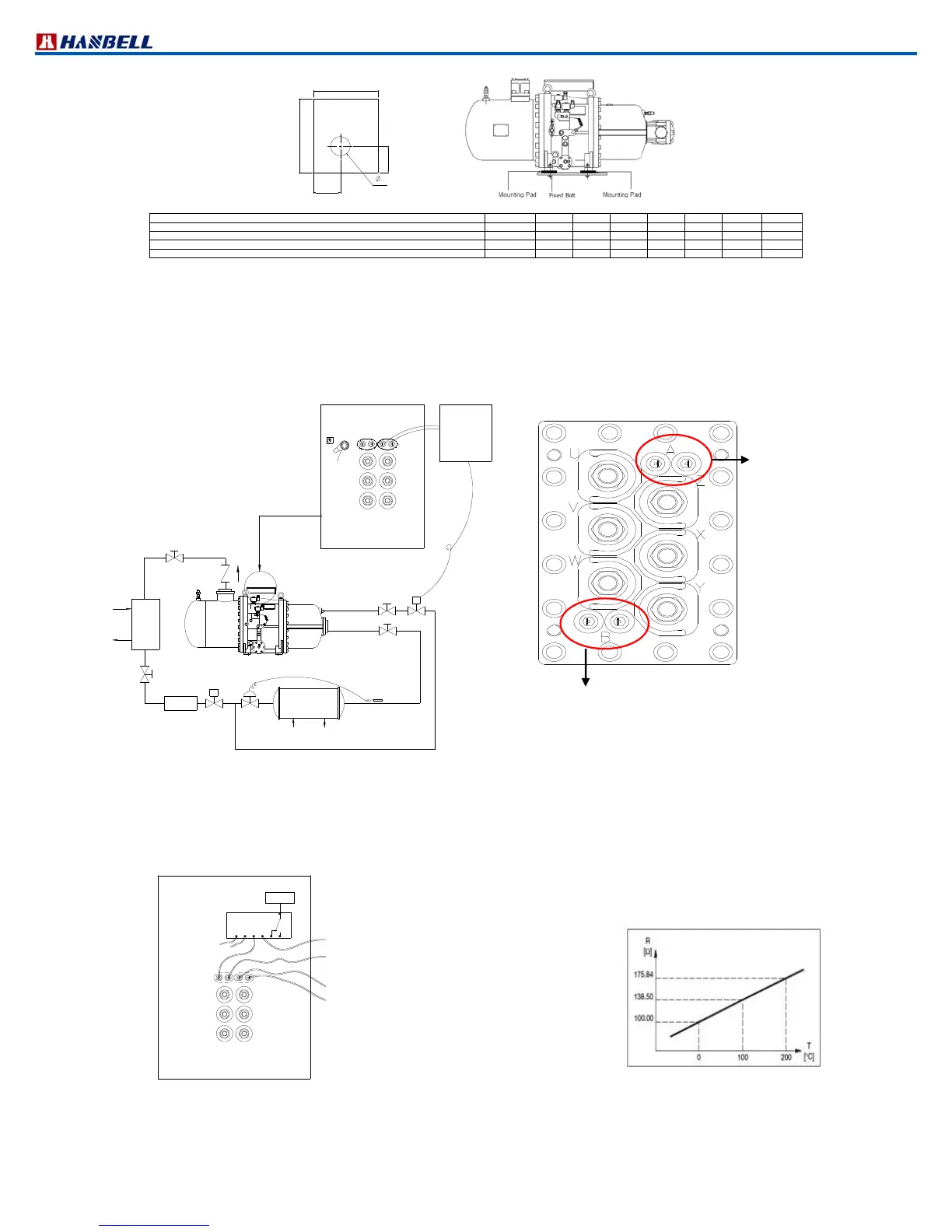
Figure 48 Compressor mounting pad (optional)
Model Part No. A B C D E Thickness
Req. Q’ty
RC2100, RC2140, RC2180, RC2200, RC2230, RC2260, RC2300, RC2310, RC2320 31319815B
20 55 50 20 22 20 mm 4
RC2340, RC2370, RC2410, RC2430, RC2470, RC2510, RC2550, RC2580 31369815B
26 100 70 25 22 20 mm 4
RC2620, RC2710, RC2790, RC2830, RC2930 31399815B
25 100 80 25 22 20 mm 4
RC21020, RC21130, RC21270, RC21530 31429815B
40 100 80 40 22 20 mm 4
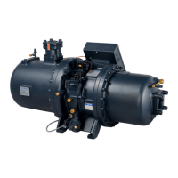
s. Temperature sensors Pt100 or Pt1000
RC2 models utilize suction return gas to cool down the motor coil. To effectively detect temperature of motor coil
and adequately adjust volume of liquid injection by measured temperature, Hanbell specially mounts Pt100 or
Pt1000 sensor on motor coil as an optional accessory. This temperature sensor along with controller of the system
monitor motor coil temperature and then control on/off of liquid injection valve accordingly to provide suitable liquid
injection as shown in the diagram below.
s
Condensor
s
Evaporator
Dryer
Chiller
in
Chiller
out
W
U
Earth Bolt
V
B:Pt100 / Pt1000(Optional)
A:PTC
Z
Y
X
B
A
Controller
Electric Plate
Liquid Injection S.V
Figure 49 Liquid injection connection diagram
1. Note: Hanbell suggests to control temperature of motor coil at 60℃ (not higher than 60℃)
2. On the terminal cover plates, “A” is PTC sensor, and “B” is Pt1000 or Pt100 temperature sensor.
3. The terminal cover plates for models RC2710B, RC2790B, RC2830B, RC2930A, RC2930B are
shown above. The PTC sensor is on the top right side and Pt1000 or Pt100 is on the left bottom side of
terminal cover plate.
V/2
W/3
U/1
X/8
Y/9
Z/7
A
B
B Set:Pt100/Pt1000(Optional)
A Set:PTC
connect to discharge PTC sensor
connect to temperature controller for
1.controlling the liquid injection solenoid valve
2. real motor coil temperature display
3.Another motor coil protection
(for high temperature warming or tirp)
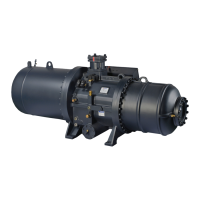
Figure 50 Connection diagram of Pt100/Pt1000 sensor Figure 51 Pt100 sensor
B: Pt1000 or Pt100