OPERATION
-15-
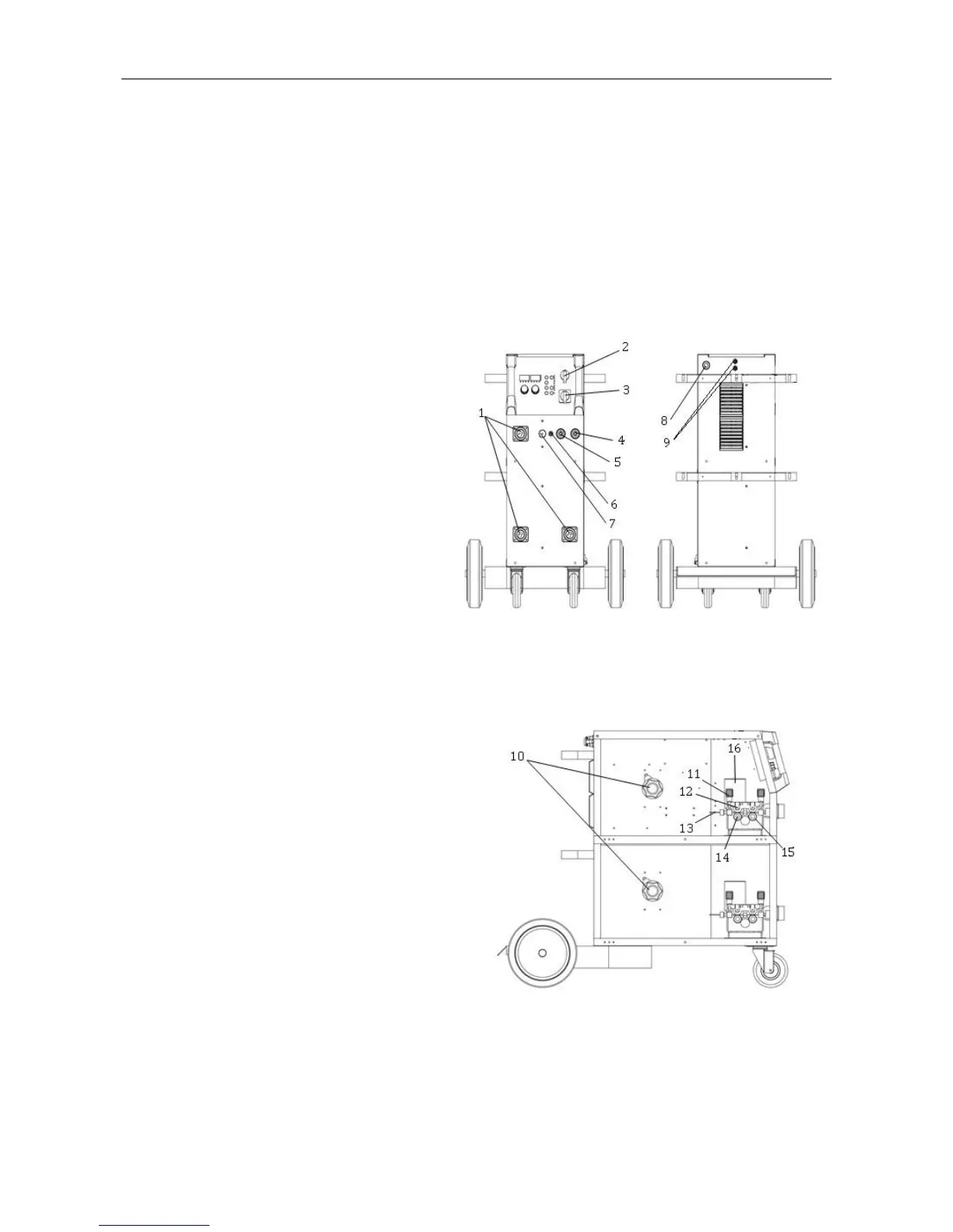
§3 Panel Functions & Descriptions
§3.1 Machine Layout Description
Front and rear panel layout of welding machine
1. MIG torch euro-connectors (3)
2. Main power ON/OFF Switch
3. Torch output “SELECT” switch (0-3)
4. Positive(+) welding power output
5. Negative(-) welding power output
6. TIG torch gas connector (5/8-18F).
7. Control circuit 9-pin connect plug.
8. Input power cord NEMA6-50P
(230VAC @ 50A Max.).
9. TIG Gas input connectors(above).
MIG Gas input connectors(below).
Wire feed cabinet (3) on welding
machine
10. Spool holder.
11. Wire feed tension adjustment (2x).
12. Wire feed tension arm (2x).
13. Wire feeder inlet guide.
14. Drive roller retainer (2x).
15. Wire drive roller (2x).
16. Wire feed motor.
 Loading...