OPERATION
-16-
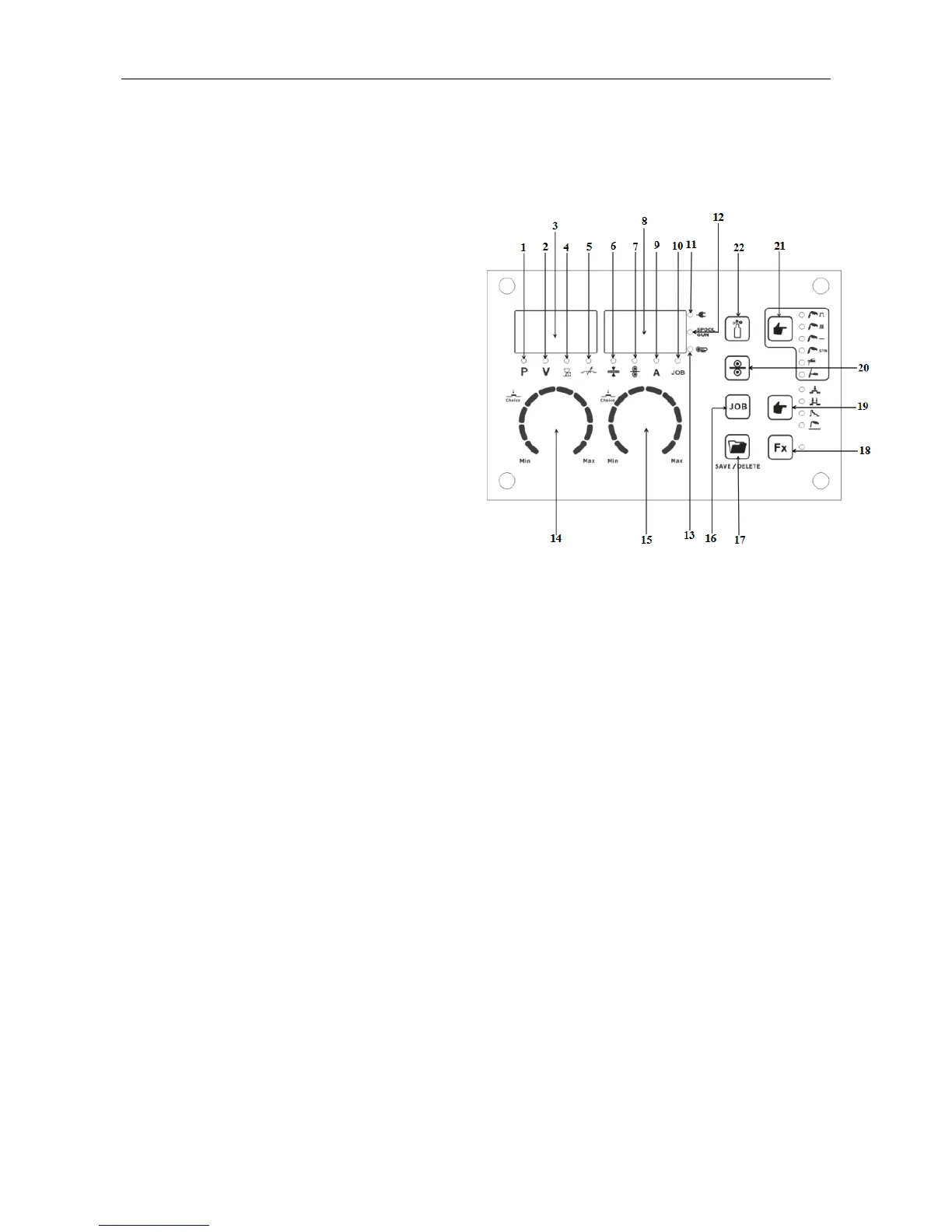
§3.2 Control panel of welding machine
1. Synergic program indicator.
2. Welding voltage indicator.
3. RH digital multifunction display.
4. Arc length indicator.
5. Inductance indicator.
6. Material thickness indicator.
7. Wire feed indicator.
8. LH digital multifunction display.
9. Welding current indicator.
10. JOB indicator.
11. Power “ON” indicator.
12. Spool gun mode indicator.
13. Over-temp alarm indicator.
14. LH parameter select/adjust knob.
15. RH parameter select/adjust knob.
16. JOB button.
17. Program save/delete button.
18. Function button.
19. Trigger mode select button: Select 2T/4T/S4T/Spot Weld
20. Manual wire feed button.
21. Welding process select button.
22. Manual shield gas check button.
Arc Length (4)
If arc length is decreased, the arc cone becomes narrower and the arc more focused
resulting in a weld bead that is narrow with slightly decreased penetration. Conversely, if
arc length is increased, the arc cone and the arc are wider resulting in a weld bead that is
wider and flatter with slightly increased penetration. Wire speed must be constant (preset
synergic) for arc length adjustment to have the desired effect on the weld.
Inductance / Wave Form (5)
Inductance slows the rate of current rise. A high inductance setting (+10) increases the
time of each arc cycle creating more penetration. A low inductance setting (-10)
decreases the time of each individual arc cycle creating a narrow bead or less
blow-through on thin material.


 To Next Page