EasyManua.ls Logo

Hankscraft Runxin RevV4 User Manual

Hankscraft Runxin RevV4
57 pages
To Next Page IconTo Next Page
To Previous Page IconTo Previous Page
Page #14 background image
RevV4 Valves & Systems Service Manual
14
Hankscraft Runxin, LLC 300 Wengel Drive 608.524.9465 hrh2o.com sales@hrh2o.com
Control Valve Configuration (refer to chart on Page 13 for specific recommendations)
Drain Line Flow Control (DLFC) Button Installation
If you wish to change the DLFC button, unscrew drain barb collar and remove drain barb.
Remove current DLFC button and replace with desired DLFC button.
Replace drain barb and tighten down drain barb collar.
Brine Line Flow Control (BLFC) Button Installation
If you wish to change the BLFC button, remove brine connector clip and then brine connector from valve.
Remove current BLFC button and replace with desired BLFC button.
Replace brine connector to valve and insert brine connector clip.
Injector Throat and Nozzle Installation
If you wish to change the injector, unscrew the two screws from the injector body and remove the cover.
Unscrew, in a counter-clockwise direction, remove the nozzle and throat.
Replace with desired nozzle and throat. Tighten in a clockwise direction until seated.
Take care not to over tighten or strip the parts.
6. Bypasses
Ceramic Bypass – 41206 / 41207
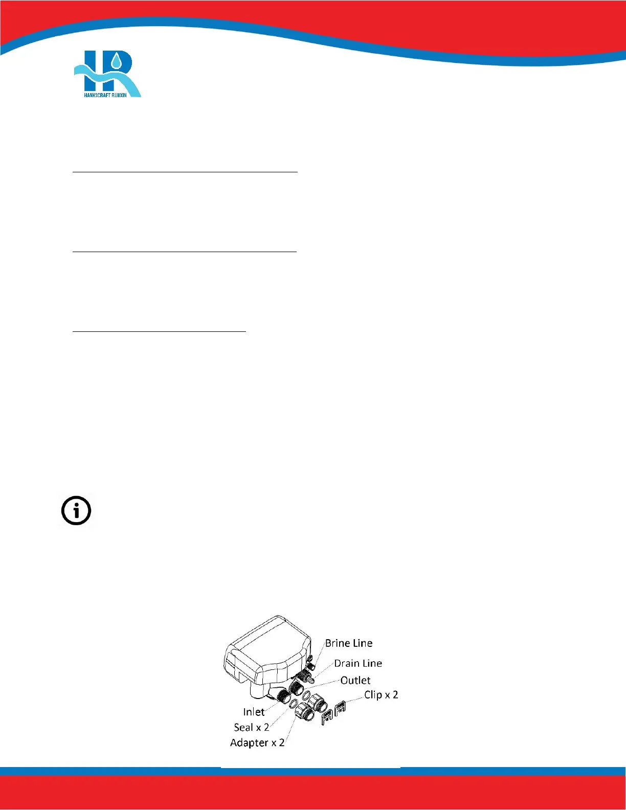
Before attaching the bypass to the valve, verify the meter is installed into the outlet side of the bypass
with the impeller facing in.
As Figure 5-2 shows; install the seals into the animated connector.
Attach animated connectors to the inlet/outlet and grease the O-rings.
Attach the bypass valve and insert the clips.
Meter cable is installed into cable port on outlet side during system start-up. See Pages 38-39.
Figure 5-2
Question and Answer IconNeed help?

Do you have a question about the Hankscraft Runxin RevV4 and is the answer not in the manual?

Hankscraft Runxin RevV4 Specifications

General IconGeneral
BrandHankscraft Runxin
ModelRevV4
CategoryControl Unit
LanguageEnglish

Summary

2. Product Features and Applications

3. Product Dimensions and Specifications

4. Pre-Installation Checklist

5. Valve Installation

Control Valve Installation

Step-by-step guide for installing the control valve onto the mineral tank.

6. Bypasses

7. Programming: Display and Instructions

Basic Programming

Adjust time values for each phase of operation.

Mode A-01: Meter Delay

Configures regeneration based on capacity and time delay.

Mode A-02: Meter Immediate

Configures immediate regeneration upon reaching zero capacity.

Mode A-03: Intelligent Meter Delay

Intelligent delay mode using capacity, hardness, and people count.

Mode A-04: Intelligent Meter Immediate

Intelligent immediate mode using capacity and hardness.

Mode A-05: Remaining Compare

Compares usage to historical data for regeneration timing.

Mode A-06: By Day (Timer)

Regeneration based on programmed service days and time.

Mode A-07: Filter Meter

Filter mode regeneration based on capacity and time.

8. PCB Functions and Connections

9. System Installation

System Start-Up

Steps to follow for initial system start-up and verification.

10. Assembly Drawings and Parts List

11. Troubleshooting

Control Valve Troubleshooting

Lists common problems and their solutions for the control valve.

Electronics Troubleshooting

Addresses issues related to the control valve's electronic components and display.

12. Replacement Parts

15. Hankscraft Runxin, LLC Warranty Statement

16. System Configuration and Settings

17. Factory Default Settings