RevV4 Valves & Systems Service Manual
25
Hankscraft Runxin, LLC 300 Wengel Drive 608.524.9465 hrh2o.com sales@hrh2o.com
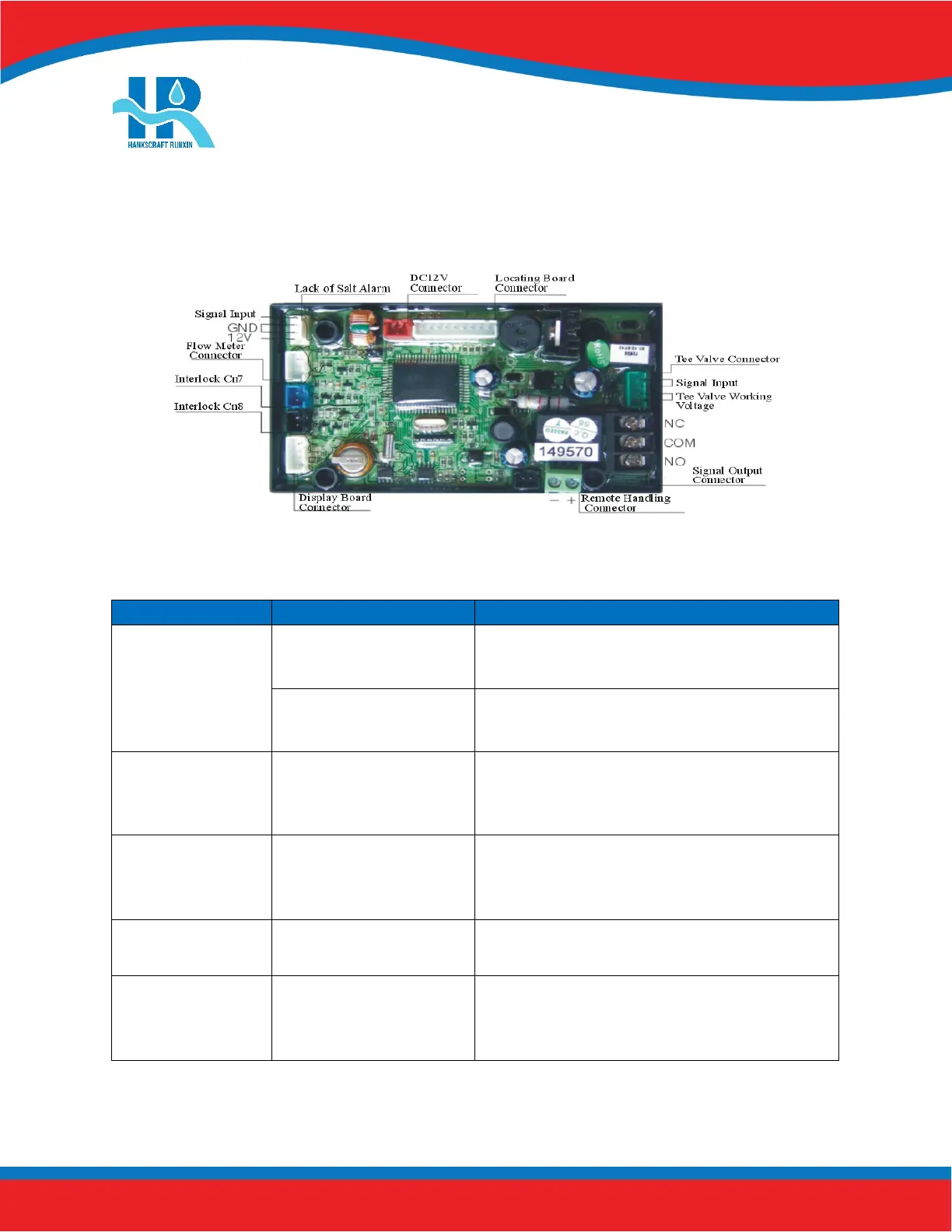
8. PCB Functions and Connections
Overview
Function Application Explanation
Signal Output
Connector b-01
Outlet solenoid valve
Optional to prevent water flow from outlet or
controlling a liquid level holding tank.
Inlet pump
Increase pressure for regeneration or backwash.
Use a liquid level controller to control inlet pump.
Signal Output
Connector b-02
Inlet solenoid valve or
inlet pump
When inlet pressure is high, a solenoid shut off
can be used to protect the valve during
regeneration.
3-Way Ball
Valve Drive
Motorized 3-way
ball valve
With alternating interlock the ball valve actuates
to supply water to one valve while another is on
standby.
Interlock Connector Used for a series of valves
Only one valve in a series can regenerate at
a time.
Remote Handling
Connector
Accepts input for
regeneration from
external source
A PLC or computer is allowed to dictate
regeneration functions for the valve.
 Loading...