EasyManua.ls Logo

Hankscraft Runxin RevV4 User Manual

Hankscraft Runxin RevV4
57 pages
To Next Page IconTo Next Page
To Previous Page IconTo Previous Page
Page #27 background image
RevV4 Valves & Systems Service Manual
27
Hankscraft Runxin, LLC 300 Wengel Drive 608.524.9465 hrh2o.com sales@hrh2o.com
Signal Output Connector
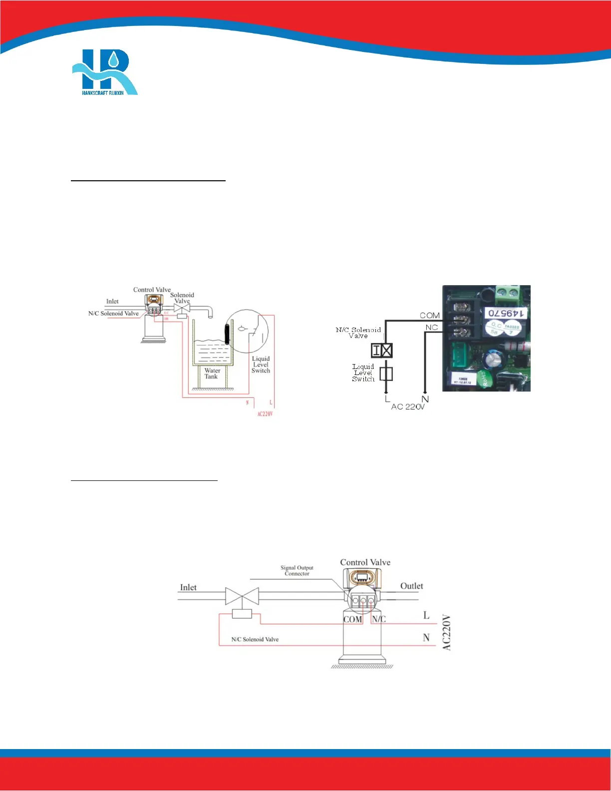
Solenoid Valve on Outlet (set b-01)
Function: Valve is normally open. When the RevV4 is in backwash there is no signal output. The solenoid valve is
closed and no water flows through the RevV4 to the holding tank.
Refer to Figure 8-1 to connect a solenoid valve for the purpose of shutoff during regeneration.
Solenoid Valve on Inlet (set b-02)
Function: When inlet pressure exceeds 125 psi, install a solenoid valve on the inlet to switch off the flow to
the valve during regeneration.
Figure 8-2 Wiring of Solenoid Valve on Inlet
Figure 8-1 Solenoid Valve on Outlet
Question and Answer IconNeed help?

Do you have a question about the Hankscraft Runxin RevV4 and is the answer not in the manual?

Hankscraft Runxin RevV4 Specifications

General IconGeneral
BrandHankscraft Runxin
ModelRevV4
CategoryControl Unit
LanguageEnglish

Summary

2. Product Features and Applications

3. Product Dimensions and Specifications

4. Pre-Installation Checklist

5. Valve Installation

Control Valve Installation

Step-by-step guide for installing the control valve onto the mineral tank.

6. Bypasses

7. Programming: Display and Instructions

Basic Programming

Adjust time values for each phase of operation.

Mode A-01: Meter Delay

Configures regeneration based on capacity and time delay.

Mode A-02: Meter Immediate

Configures immediate regeneration upon reaching zero capacity.

Mode A-03: Intelligent Meter Delay

Intelligent delay mode using capacity, hardness, and people count.

Mode A-04: Intelligent Meter Immediate

Intelligent immediate mode using capacity and hardness.

Mode A-05: Remaining Compare

Compares usage to historical data for regeneration timing.

Mode A-06: By Day (Timer)

Regeneration based on programmed service days and time.

Mode A-07: Filter Meter

Filter mode regeneration based on capacity and time.

8. PCB Functions and Connections

9. System Installation

System Start-Up

Steps to follow for initial system start-up and verification.

10. Assembly Drawings and Parts List

11. Troubleshooting

Control Valve Troubleshooting

Lists common problems and their solutions for the control valve.

Electronics Troubleshooting

Addresses issues related to the control valve's electronic components and display.

12. Replacement Parts

15. Hankscraft Runxin, LLC Warranty Statement

16. System Configuration and Settings

17. Factory Default Settings