EasyManua.ls Logo

Hankscraft Runxin RevV4 User Manual

Hankscraft Runxin RevV4
57 pages
To Next Page IconTo Next Page
To Previous Page IconTo Previous Page
Page #29 background image
RevV4 Valves & Systems Service Manual
29
Hankscraft Runxin, LLC 300 Wengel Drive 608.524.9465 hrh2o.com sales@hrh2o.com
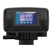
Function: When the RevV4 is in service and the water level in the tank is low the pump starts up. If the water
tank has enough water the switch for the liquid level controller is closed and the pump turns off. When the
RevV4 is in regeneration the inlet always requires water. A safety switch should be installed in the holding
tank so the pump does not go dry.
Liquid Level Switch in Water Tank Controls Inlet Pump (three-phase) (set b-01)
Figure 8-5 Wiring of Liquid Level Switch in the Holding Tank with the Pump on the Inlet.
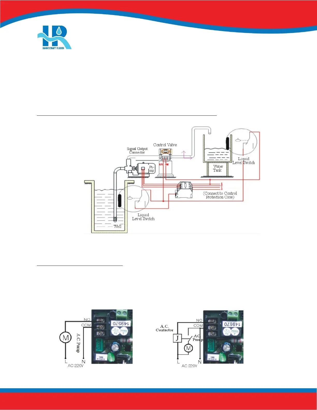
Inlet Booster Pump (set b-01 or b-02)
Function: If inlet water pressure is less than 20 psi, install a pump on the inlet side of the RevV4; usually set
for control mode b-01. When the RevV4 valve is in regeneration, the booster pump is open and active. If the
booster pump current is greater than 5A, an external contact is required. Refer to Figure 8-6 and 8-7.
Figure 8-6 Schematic of output to a pump < 5A. Figure 8-7 Schematic of output to a pump > 5A. Incorporates relay.
Question and Answer IconNeed help?

Do you have a question about the Hankscraft Runxin RevV4 and is the answer not in the manual?

Hankscraft Runxin RevV4 Specifications

General IconGeneral
BrandHankscraft Runxin
ModelRevV4
CategoryControl Unit
LanguageEnglish

Summary

2. Product Features and Applications

3. Product Dimensions and Specifications

4. Pre-Installation Checklist

5. Valve Installation

Control Valve Installation

Step-by-step guide for installing the control valve onto the mineral tank.

6. Bypasses

7. Programming: Display and Instructions

Basic Programming

Adjust time values for each phase of operation.

Mode A-01: Meter Delay

Configures regeneration based on capacity and time delay.

Mode A-02: Meter Immediate

Configures immediate regeneration upon reaching zero capacity.

Mode A-03: Intelligent Meter Delay

Intelligent delay mode using capacity, hardness, and people count.

Mode A-04: Intelligent Meter Immediate

Intelligent immediate mode using capacity and hardness.

Mode A-05: Remaining Compare

Compares usage to historical data for regeneration timing.

Mode A-06: By Day (Timer)

Regeneration based on programmed service days and time.

Mode A-07: Filter Meter

Filter mode regeneration based on capacity and time.

8. PCB Functions and Connections

9. System Installation

System Start-Up

Steps to follow for initial system start-up and verification.

10. Assembly Drawings and Parts List

11. Troubleshooting

Control Valve Troubleshooting

Lists common problems and their solutions for the control valve.

Electronics Troubleshooting

Addresses issues related to the control valve's electronic components and display.

12. Replacement Parts

15. Hankscraft Runxin, LLC Warranty Statement

16. System Configuration and Settings

17. Factory Default Settings