EasyManua.ls Logo

Hankscraft Runxin RevV4 User Manual

Hankscraft Runxin RevV4
57 pages
To Next Page IconTo Next Page
To Previous Page IconTo Previous Page
Page #34 background image
RevV4 Valves & Systems Service Manual
34
Hankscraft Runxin, LLC 300 Wengel Drive 608.524.9465 hrh2o.com sales@hrh2o.com
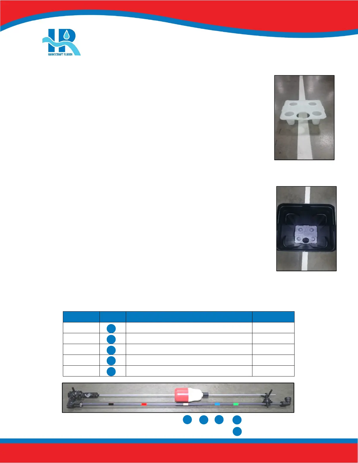
3. Assemble salt grid (4 feet, 1 base). Feet clip into the bottom of the base.
4. Insert assembled salt grid into brine tank by lining up the cut out hole with
the drilled holes on the brine tank.
5. Hold float and connected ABS tubing (at the bottom; securing the ABS tubing), turn the black nut
counterclockwise while the tubing is secured in place. Set to desired salt setting and retighten float nut.
Tank Size
Letter
Salt Level (See Fig. 4) Salt Setting
9x48
To white tape or above 9 lbs.
10x44
Halfway between white/blue tape or above ~ 10.5 lbs.
10x54
To blue tape or above 12 lbs.
12x52
To green tape or above 15 lbs.
13x54
To green tape or above > 15 lbs.
A
B
C
D
E
A
B
C
D
E
Question and Answer IconNeed help?

Do you have a question about the Hankscraft Runxin RevV4 and is the answer not in the manual?

Hankscraft Runxin RevV4 Specifications

General IconGeneral
BrandHankscraft Runxin
ModelRevV4
CategoryControl Unit
LanguageEnglish

Summary

2. Product Features and Applications

3. Product Dimensions and Specifications

4. Pre-Installation Checklist

5. Valve Installation

Control Valve Installation

Step-by-step guide for installing the control valve onto the mineral tank.

6. Bypasses

7. Programming: Display and Instructions

Basic Programming

Adjust time values for each phase of operation.

Mode A-01: Meter Delay

Configures regeneration based on capacity and time delay.

Mode A-02: Meter Immediate

Configures immediate regeneration upon reaching zero capacity.

Mode A-03: Intelligent Meter Delay

Intelligent delay mode using capacity, hardness, and people count.

Mode A-04: Intelligent Meter Immediate

Intelligent immediate mode using capacity and hardness.

Mode A-05: Remaining Compare

Compares usage to historical data for regeneration timing.

Mode A-06: By Day (Timer)

Regeneration based on programmed service days and time.

Mode A-07: Filter Meter

Filter mode regeneration based on capacity and time.

8. PCB Functions and Connections

9. System Installation

System Start-Up

Steps to follow for initial system start-up and verification.

10. Assembly Drawings and Parts List

11. Troubleshooting

Control Valve Troubleshooting

Lists common problems and their solutions for the control valve.

Electronics Troubleshooting

Addresses issues related to the control valve's electronic components and display.

12. Replacement Parts

15. Hankscraft Runxin, LLC Warranty Statement

16. System Configuration and Settings

17. Factory Default Settings