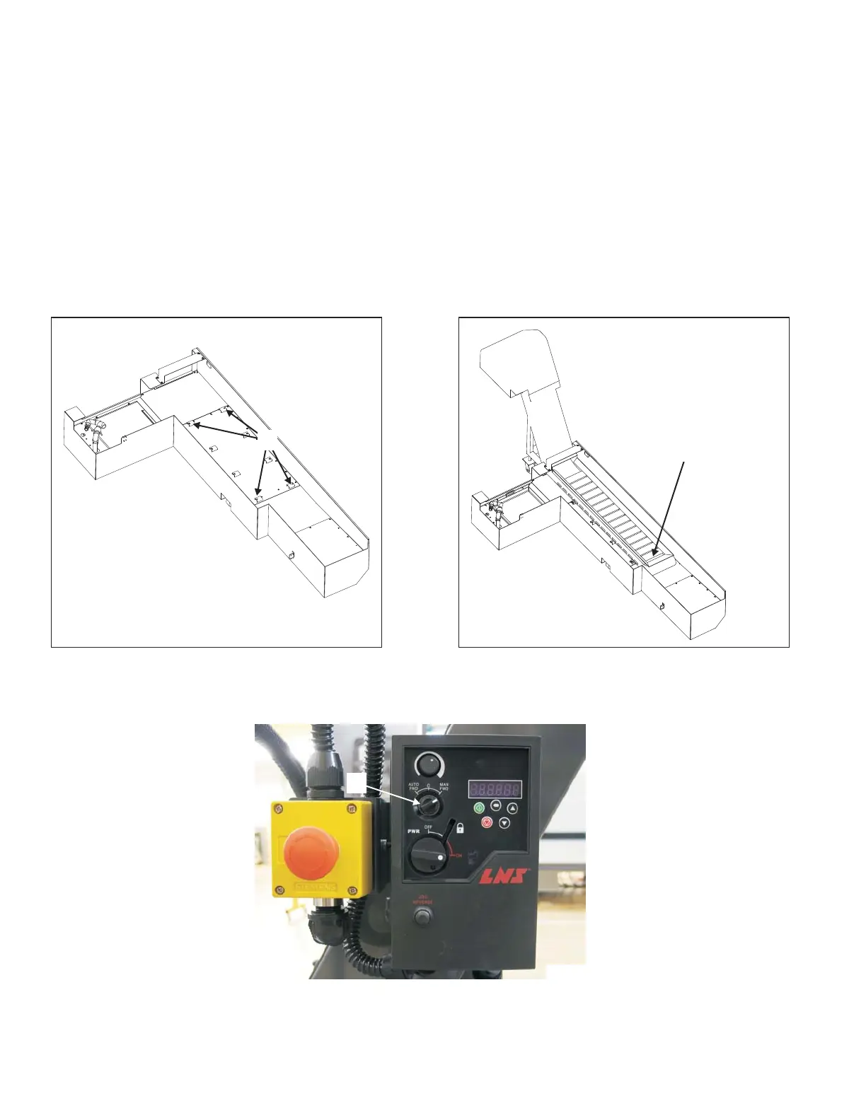
COOLANT TANK INSTALLATION
1. If the machine is equipped with a chip conveyor:
T-42 LATHE
A) Remove four screws "K", Figure 1.39, from the coolant tank.
B) Support the left end of the chip conveyor.
C) Roll the chip conveyor into the coolant tank. Refer to Figure 1.40.
D) Secure the chip conveyor with the four screws previously removed.
E) Set bar feed selector switch "L", Figure 1.41, to MAN FWD (Manual Forward).
1-24 M-507C
Figure 1.39 - Chip Conveyor Coolant Tank
(T-42 Lathe)
K
TI5791
Figure 1.40 - Chip Conveyor Installed
(T-42 Lathe)
Support this end of
the chip conveyor
during installation.
TI5789
Figure 1.41 - Chip Conveyor Control Box
TP8309
L