- NOTE -
Connection information can also be referenced in the schematic suppled with the
machine.
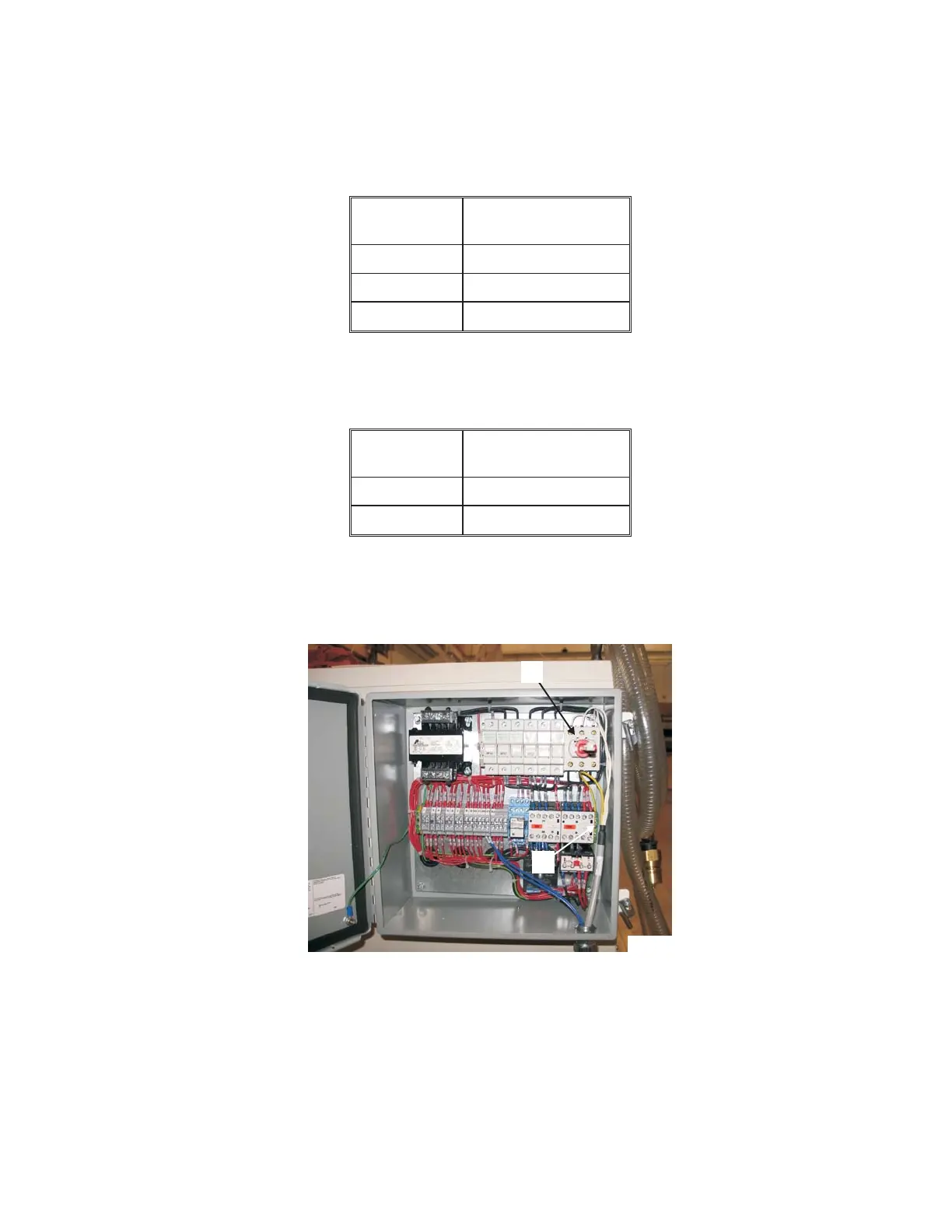
7. Connect the white power wires in cable 500CBL to the top of circuit breaker "G", Figure 1.52, as
follows:
Wire
Number
Circuit Breaker
Connection
1L1
2L2
3L3
8. Connect the ground wire (green/yellow) to ground terminal block “H” (green/yellow).
9. Connect the blue signal wires to the terminal strip as follows:
Wire
Number
Terminal Strip
Connection
5736 20
+24A 21
M-507C 1-29
Figure 1.52 - Coolant Chiller
Electrical Connections
TP8081
G
H