| www.harmar.com | 800-833-0478 © 2016 Harmar All Rights Reserved
24
INSTALLER
CAM
CAM
Rotation
Limit
Switches
Set screw
Setscrew
Rotation Limit
Switches may
also need to be
ipped,toproperly
stop the motor.
Figure 24-3Figure 24-1 Figure 24-2
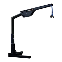
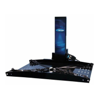
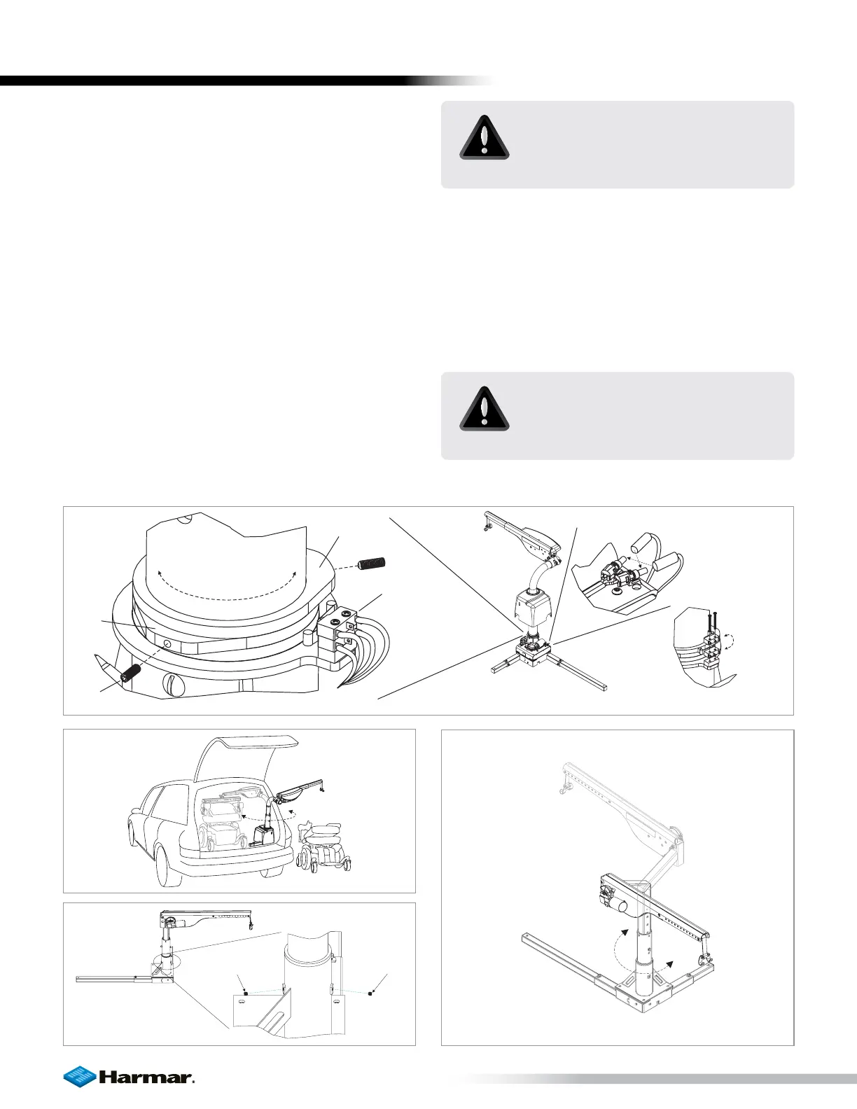
ADJUSTMENTS : ROTATION
AL225 / AL425 / AL435 / AL 435T
The amount of allowable rotation is determined by
the cams indicated below. Loosen set screw and
rotate as required. [Figure 24-1]
If installing the lift on the driver side, or if the post
rotates in the wrong direction, simply reverse the wires
at the rotational motor. [Figure 24-2]
Rotation Limit Switches may also need to be flipped
to properly stop the motor. [Figure 24-3]
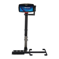
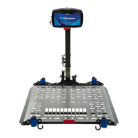
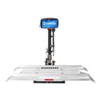
The average installation will require approximately 180
degrees of rotation. [Figure 24-4]
Set the rotation so that the arm has enough room
to transport the mobility device in and out of the
vehicle without any contact with the vehicle.
Set screw
Set screw
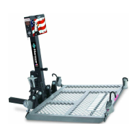
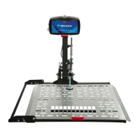
AL215
The AL215 is manufactured with manual rotation.
The base has two set screws which act as mechanical
stops to limit the rotation of the arm. [Figure 24-5]
When the arm is rotated, it should stop at its full in
and out positions. [Figure 24-6]
LIFT ADJUSTMENTS
CAUTION!
Do not set the limits to over rotate
the arm. Damage may occur to the
vehicle.
CAUTION!
Be sure that set screws are in place,
but not so tight as to prohibit the
arm from rotating.
Figure 24-4
Figure 24-5 Figure 24-6