SETTING DIP SWITCH IN CASE OF 2 HA
YWARD POOL SYSTEM CONTROLS INSTALLED NEAR ONE ANOTHER:
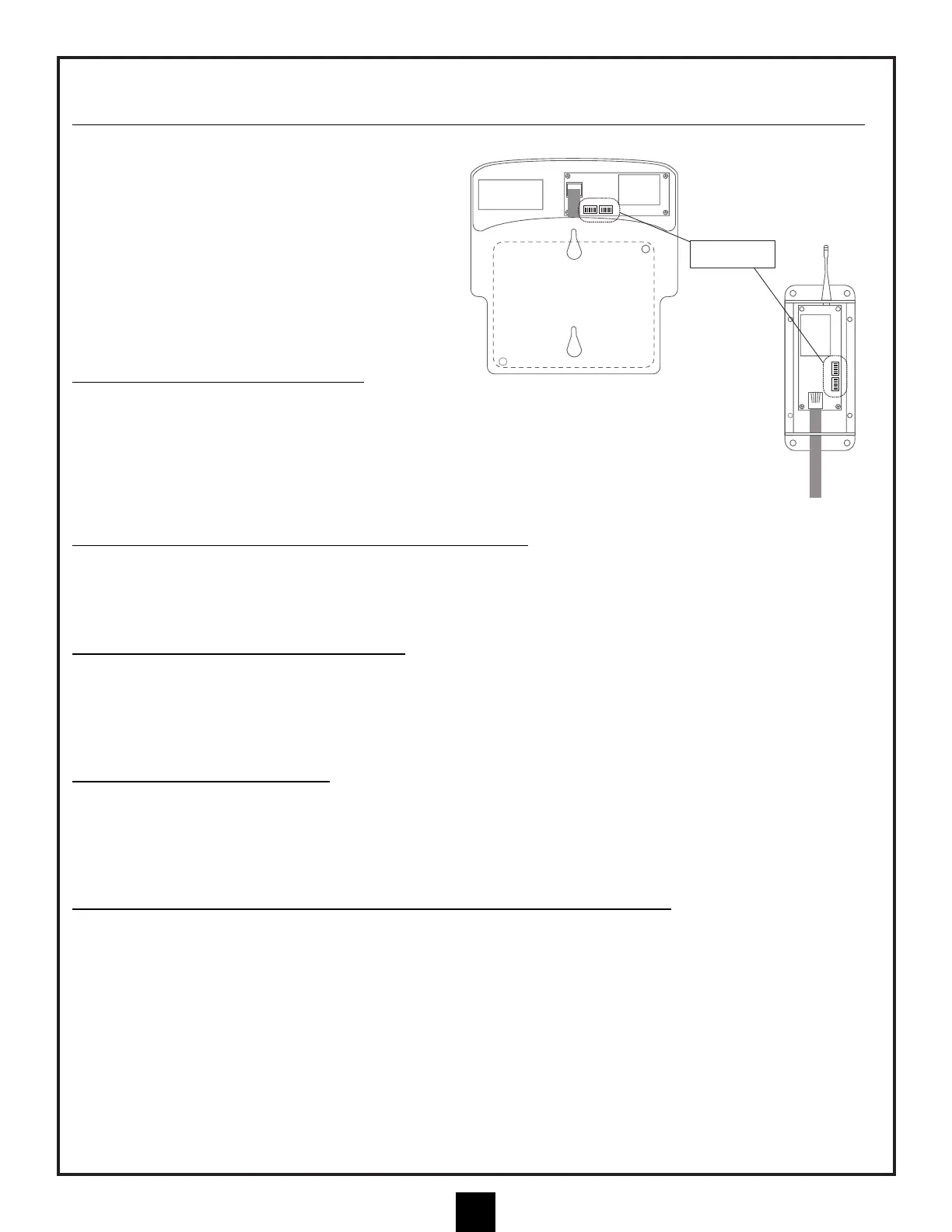
Note: There are DIP switches on the circuit board,
inside the Receiver Modules, that are always
shipped in the OPEN position. In the event that two
Hayward wireless control systems are installed near
one another, these switches can be used to create a
unique "code" that your control will communicate
under. This will minimize the possibility of any
"crosstalk" between systems.
IMPORTANT: THE SWITCHES MUST BE SET THE
SAME WAY IN BOTH THE RECEIVER MODULE AND
THE MASTER PANEL RF CRADLE.
INST
ALL RF MASTER PANEL CRADLE:
The RF Master Panel Cradle is battery operated and is
ready to operate once the existing "RF-ready" Master Panel is
installed in it. The unit is supplied with the internal DIP switches set to OPEN so it is compatible with
the RF board described above. The RF Master Panel will turn on when either the Up or Down button
is pressed once. When it is on, it should behave just as if it were hard-wired. If a button is not pressed
for 3 minutes, the panel will "sleep" to preserve battery life.
USING A TRANSFORMER FOR RF MASTER P
ANEL CRADLE:
A plug-in transformer option is available that allows the panel to be "awake" at all times and display pool functions
without the need to activate the panel first. The plug in connector for the transformer can be used by removing the
battery cover and plugging the transformer wire into the circuit board and then routing the wire out of the battery
compartment through an upper or lower opening.
INST
ALL RF MASTER PANEL INTO CRADLE:
To install an RF-ready Master Panel in the RF Cradle, first turn the Master Panel over and remove the upper right
and lower left screws that are obvious on the back of the panel. These screws will be replaced by the longer screws
included with the RF Cradle. Plug the phone-type wire from the RF Cradle into the Master Panel. Carefully lay the
Master Panel into the RF Cradle and install the new, longer screws through the RF Cradle and into the Master
Panel, being careful not to overtighten.
INST
ALL BATTERY INTO CRADLE:
Open the battery compartment by removing the cover screws and tilting the door away from the RF Cradle. Install 4
AA batteries in the battery holder and plug the battery holder into the circuit board. (At this time, the optional
transformer can be installed if desired, in which case batteries are not required.) The installation is now complete.
The antenna is able to rotate on the side of the RF Cradle and should be in a vertical orientation when the panel is
in use.
MOUNT RF MASTER CONTROLLER (CRADLE WITH MASTER P
ANEL) ON WALL:
If you intend to mount the RF panel on a wall, mark the locations of the mounting holes BEFORE the Master Panel
is installed in the Cradle. You may wish to choose a location close to a wall outlet so that the optional wall
transformer can be used to power the unit.