Mechanical installation
C9C A03729_03_YI0_01 HBM: public 17
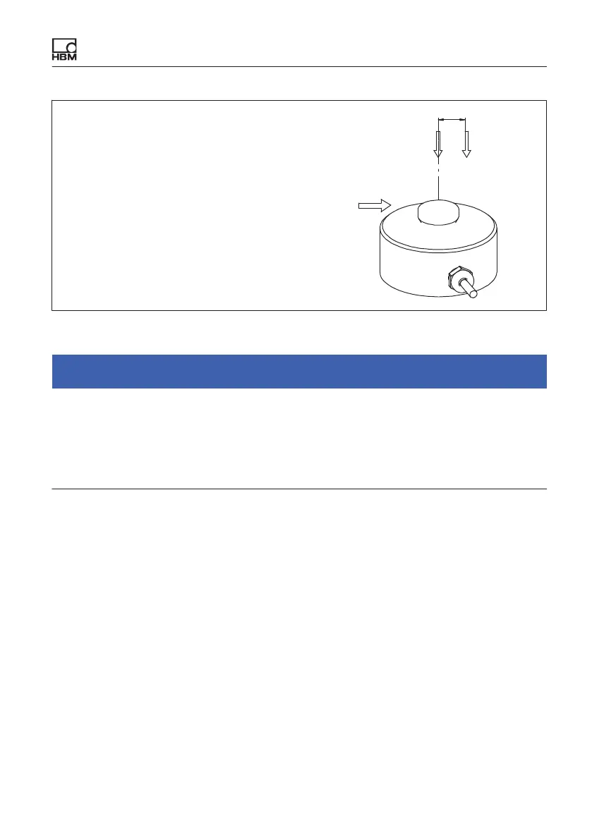
F
nom
Force in direction of measurement
F
ex
Force in direction of measurement, out
side the center of the force transducer
e Eccentricity (center of force transducer -
force application distance)
F
nom F
ex
Fq
e
Fig. 6.1 Parasitic forces and moments
Notice
When installing and operating the transducer, please note the maximum
parasitic forces - lateral forces (due to oblique application), bending moments
(due to eccentric force application) and torques, see the Specifications section
9 on page 29, and the maximum permissible loading capacity of the force
application parts used (possibly provided by the customer).
Load is applied via the spherical load button on top of the force transducer.
The structural component that applies the force to the convex load application
part must be ground and have a hardness of at least 40 HRC.
HBM provides EDO9 thrust pieces for the C9C, which are used to keep
torques and bending moments away from the transducer. The thrust pieces
naturally have the correct hardness and surface quality.