T12
22
A1979−10.0 enHBM
Important
Use a threadlocker (medium strength, e.g. LOCTITE) to glue the connecting
screws into the counter thread.
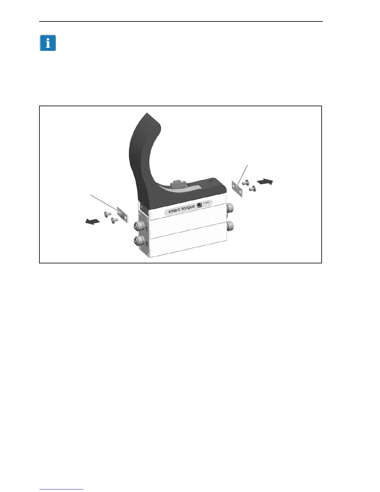
1. Remove the side cover plates on the stator housing (see Fig. 6.4.)
Cover plate
Cover plate
Fig. 6.4: Cover plates on the stator housing
2. Only for measuring ranges 500 N@m to 3 kN@m and subsequently
ordered protection against contact: some of the tapped holes for the
locking screws are covered by attached film. Make a semicircular cutout in
the film here, with a minimum radius of 6 mm (use a cutter, as shown in
Fig. 6.5, for example).
Now remove the threaded pins from the tapped holes on both sides of the
stator.


 To Next Page