Mechanical installation
T40B A3452-10.0 29
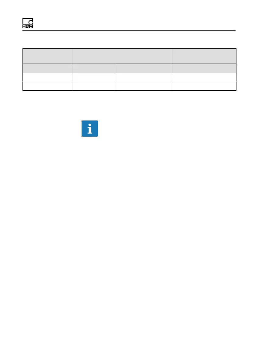
Prescribed tightening
moment
Fastening screwsMeasuring range
NVmProperty classZ
1
NVm
5 k M14 12.9 220
10 k M16 12.9 340
1)
DIN EN ISO 4762; black/oiled/m
tot
= 0.125
Tab. 5.1 Fastening screws
Important
Dry screw connections can result in different and higher
friction factors (see VDI 2230, for example). This means
a change to the required tightening moments. The
required tightening moments can also change if you use
screws with a surface or property class other than that
specified in Tab. 5.1, as this affects the friction factor.
5.6 Installing the stator
On delivery, the stator has already been installed and is
ready for operation. The upper antenna segment can be
separated from the stator, for example, for maintenance
or to facilitate stator mounting, only for Option 7, Code S.
If your application does not require the stator to be dis
mantled, proceed as described in points 2., 5., and 6 for
Option 7, Code S.
 Loading...