Electrical connection
42 A3452-10.0 T40B
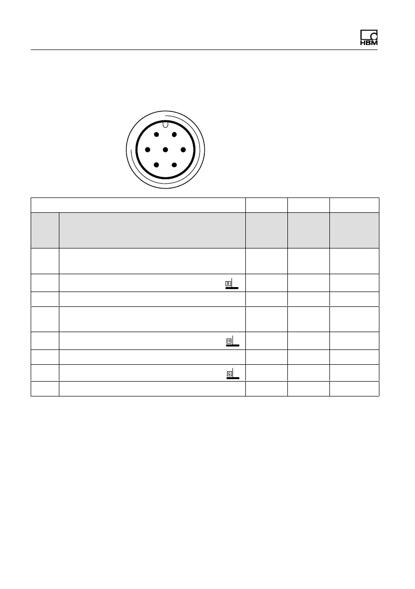
Assignment for plug 1 - Supply voltage and
frequency output signal
61
5 72
4
3
Device plug
Top view
KAB153 KAB149 KAB178
1)
Plug
pin
Assignment Color
code
D‐SUB‐
plug
pin
HD‐SUB‐
plug
pin
1
Torque measurement signal (frequency
output; 5 V
2,3
)
wh 13 5
2
Supply voltage 0 V;
bk 5 -
3 Supply voltage 18 V to 30 V bu 6 -
4
Torque measurement signal (frequency
output; 5 V
2,3
)
rd 12 10
5
Measurement signal 0 V; symmetrical
gy 8 6
6 Shunt signal trigger 5 V to 30 V gn 14 15
7
Shunt signal 0 V
gy 8 -
Shielding connected to housing ground
1)
Bridge between 4 + 9
2)
RS-422 complementary signals; with cable lengths exceeding 10 m, we recommend using a
termination resistor R = 120 ohms between the (wh) and (rd) wires.
3)
RS‐422: pin 1 corresponds to A, pin 4 corresponds to B.