Electrical connection
VK20A A2335-2.0 HBM: public 21
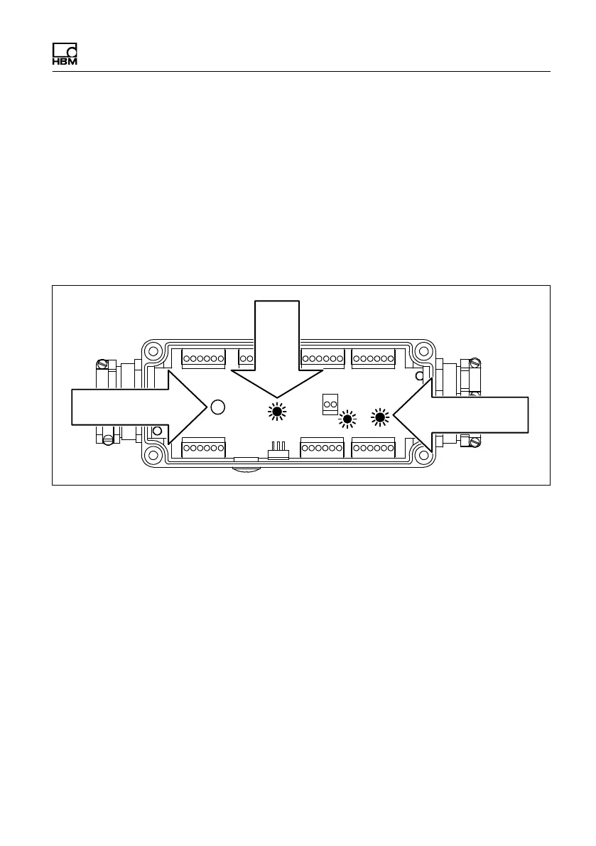
5.1.8 Functional check
Three green control diodes for checking the wiring and a
control signal push button (for T20WN, T21WN) are inte
grated in the junction box.
Diode A1 comes on whenever a stabilized supply voltage
of 12 V is made available to the torque transducer. LEDs
A2 and A3 flash whenever the input shaft of the T20WN,
T21WN turns slowly.
1 61
A2
A1
161
6
1616
166
A3
S1
Control signal
Supply
voltage
Angle of rotation/
rotation speed
Fig. 5.5 Control LEDs and control signal push button
5.1.9 Control signal (T20WN, T21WN)
You can trigger a control signal of +10 V ("0.2 %):
S with push button S1 on the board (as long as it is
pressed; see Fig. 5.5).
S with an external push button or relay point on strip
terminal St7, terminals 3 and 4 (see Fig. 5.6).
S with an external voltage (5 V...30 V) at strip terminal
St7, terminals 2 and 3 (see Fig. 5.6). The input is
potential‐free by using optical couplers.