Electrical connection
14 A2335-2.0 HBM: public VK20A
5.1.1 Mechanical connection of the connector
cables
The junction box includes a set of cable sleeves,
intended for bushing the transducer connection cable, the
voltage supply and the Md/n outputs. The side hole for
the external control signal is closed with a screw for
delivery. If need be, use a suitable PG7 screwed joint
with an anti‐buckling socket.
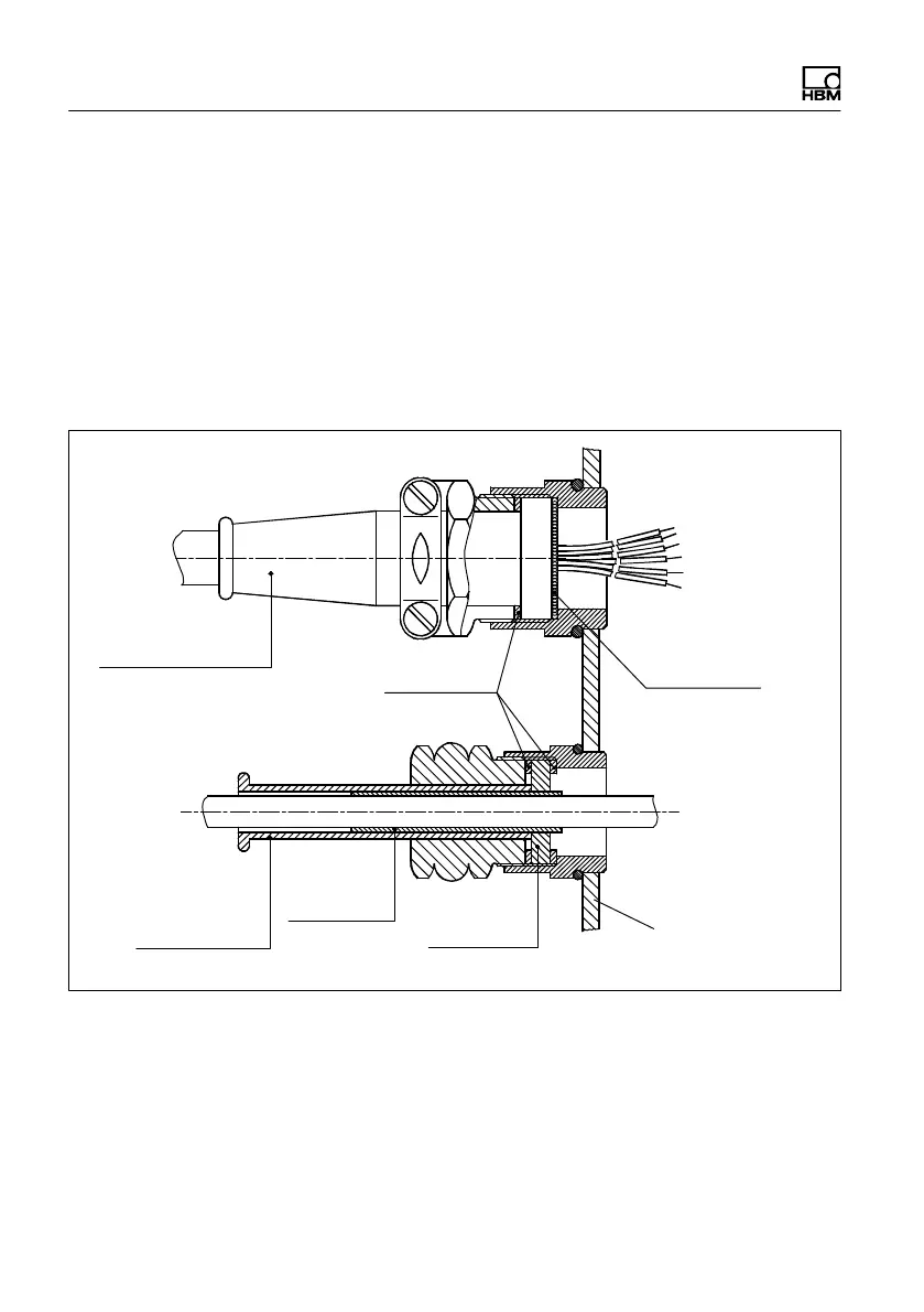
Anti‐buckling socket,
internal Ø 7 mm
Clamping ring
T20WN, T21WN, T22
Power
Cable shield
looped round
clamping ring
Anti‐buckling
socket, internal
Ø 5 mm
Cable sleeve
Rubber seal
Wall of the housing
Fig. 5.3 Cable bushing ”T20WN, T21WN, T22” and
”POWER” at the junction box