Hear Back PRO User Guide
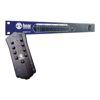
HBUS
The HBUS permits daisy-chaining of multiple Hubs up to 500 feet
apart using the HBUS input and HBUS output. This HBUS is great
for inter-studio or stage-to-stage connections, as well as daisy-
chaining for very large systems. Use Hear Technologies CAT6*
cables available in 50 foot length.
HBUS In also allows a connection to a wireless access point for
using the PRO’s iOS App.
HBUS RJ45 pin-outs are the same as standard gigabit Ethernet
RJ45 pin-outs, only without power. The pin-outs are wired as
shown below:
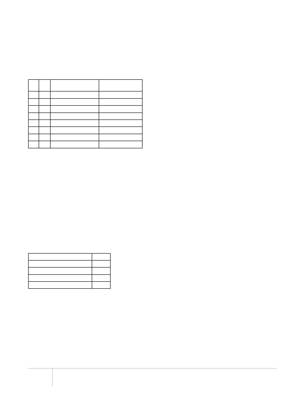
Pin Pair Description
Suggested Termination
Color Scheme (568B)****
1 A+ Bidirectional Data Pair A white/orange
2 A- Bidirectional Data Pair A orange
3 B+ Bidirectional Data Pair B white/green
4 C+ Bidirectional Data Pair C blue
5 C- Bidirectional Data Pair C white/blue
6 B- Bidirectional Data Pair B green
7 D+ Bidirectional Data Pair D white/brown
8 D- Bidirectional Data Pair D brown
****Color Scheme 568A is also acceptable, but do not crossover
from 568A to 568B.
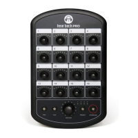
INPUT SELECTOR SWITCH
The input selector switch gives the user a simple way to select
any one of the three input/clock sources without a patch bay,
router, or rewiring.
For FW V2, switching between A and B selects 16 channels from
either A or B.
For FW V5, inputs A and B are used simultaneously. Selecting
between A and B only selects the clock source. If more than
32 channels are needed, multiple Hubs are required (see
Connecting Multiple Hubs on page 11).
INPUT METERING
The Hub features a unique input metering circuit consisting of
one RGB LED for each of the first 16 input channels. Each LED
provides four visual levels that correspond color to signal strength
in dBu:
Signal Strength Color
-36 dBu to -18 dBu RMS blue
-18 dBu to 0 dBu RMS green
0 dBu to +17.5 dBu RMS yellow
+17.5 dBu (clip) Peak red
With FW V5, the optional PRO iOS App allows the user to select
between monitoring channels 1-16 or 17-32.
STATUS INDICATING HUB LOGO
The illuminated logo serves as an indicator for several purposes.
Under normal conditions, the logo will be BLUE, indicating valid
clock is present (could be internal or external). A RED logo
indicates no valid clock is present. If the logo is blinking RED,
this typically indicates a temperature problem, but could indicate
something else. Refer to troubleshooting section for detailed
information.
INTERNAL FAN
The internal temperature-controlled fan operates whenever the
internal temperature reaches 43° C or 110° F. In studio or indoor
use, the fan should rarely come on. The Hub should be rack
mounted away from high temperature devices such as power
amplifiers. Please ensure our recommended clearances listed at
the beginning of this manual are met.
DUAL POWER PORTS
The Hub supports two external power supplies. The second power
supply serves two purposes: to provide redundancy in case of
power failure, and to power more than two network cards (greater
than 16 Mixers) in a single Hub. On the front of the Hub, an LED
directly above the power switch will be lit if two power supplies are
present. This provides an easy way to know if one of the power
supplies has failed. On the back of the Hub, an LED is present
directly under each power port, and will be lit if power is present
at that port.
4
*Cable complying with the National authorities (cable with an outer jacket or sleeving rated VW-1 or better).