Page
13
STEP-BY-STEP
ASSEMBLY
ASSEMBLY
NOTES
1
.
Before you start to assemble this kit, review
the wiring,
and soldering
information
in the "Kit Builders Guide." Also
be sure to read each
step
all the way through before performing
that step.
2.
Due
to
the
small
foil
area around some circuit board holes and
the small
areas between
foils, you must use the utmost care
to
prevent
solder bridges
between
adjacent foil areas. Use only a minimum amount of solder and
do
not heat components
excessively with the soldering iron. It is
also very
important that you keep your soldering iron
tip clean and well tinned.
Diodes, transistors,
etc., can be damaged if subjected
to
an excessive
amount of heat.
3. Resistors will be called out by their resistance
value in n or kJ2 (kilohms)
and color
code.
4.
Capacitors will be called out
by their capacitance value
(in pF or /jF) and
type (disc, mica, or ceramic).
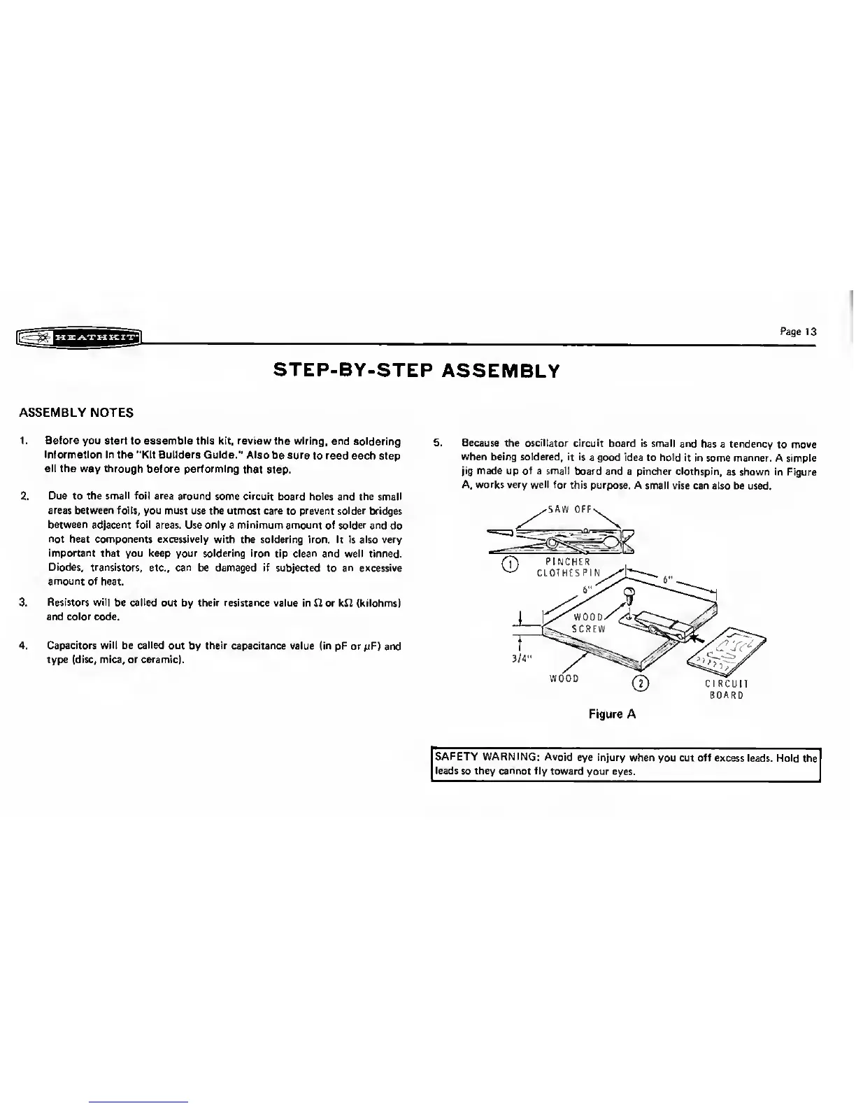
5. Because the oscillator
circuit board is
small and has
a
tendency
to move
when being soldered,
it is a
good
idea
to hold it in some manner.
A simple
jig made
up
of
a small board and
a pincher clothspin,
as
shown
in Figure
A, works very
well
for
this purpose.
A small vise can also
be used.
BOARD
Figure A
SAFETY WARNING:
Avoid
eye
injury
when you cut off
excess leads.
Hold the
leads
so they
cannot
fly toward
your eyes.