Page 26
TOP PANEL ASSEMBLY
Refer
to
Pictorial
4-1
(fold-out from Page 27)
for
the
following steps.
(
)
Remove the paper backing strips
from
the
hairline grid and,
if necessary,
any
protective film from the other side.
Then refer to Detail 4-1
A
and
carefully press the grid in place on the
inside of the
top
panel as
shown.
Be
sure the
hairline
is
exactly
centered from side
to
side as
shown.
Also, be
sure none
of the adhesive backing is exposed
in the panel openings.
( )
Carefully position
the rear of
the top
panel over the
coil
socket
on the rear
of the
chassis. Then lower the top
panel downward, carefully, over the
shaft of the pushbutton switch
and
over the top
of the meter. Slightly
spring the front edge
of
the top
panel forward, and continue sliding it
downward until the hole
in
the
front is around the phone jack as
shown in
the
Pictorial. Carefully work the meter face from side to side slightly
until
it fits properly
into
the top
panel meter opening.
NOTE: Use
the nut starter
to
hold and start
6-32
nuts
on screws.
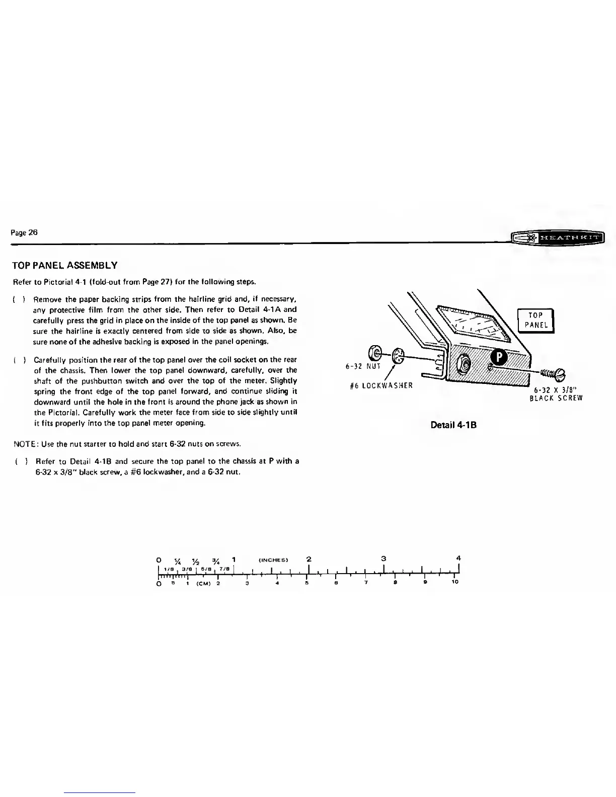
(
)
Refer
to
Detail
4-1 B
and secure the
top
panel to the
chassis at P with
a
6-32
x
3/8"
black
screw,
a #6
lockwasher, and a
6-32
nut.
3
%
Vl
V*
1
(INCHES) 2
I 1/8 .3/8
16/8
7/8 1 . I .
,
1
1 1
|
'
!
1
i
'
'
|
1
i
1
'
|
1
I
1
)' 'i
1
|
1
'
i
1
3
S
1
(CM)
2 3
4 5
BLACK
SCREW
Detail
4-1
B
3
4