8. Using an insulated screwdriver, adjust neutralizing capacitor for a MINIMUM
indication on the VTVM.
9. Readjust the neutralizing capacitor for a minimum indication on theVTVM.
10.Turn the FUNCTION switch to the off position.
11.Discharge high voltage power supply capacitors.
12.Reconnect final plates & screen grid.
**VTVM & RF probe will be needed.
***To remove screen voltage in SB-100, SB-101, HW-100 & HW-101 disconnect R920
(100 ohm resistor) from buss wire between pins of V8 & V9. In the SB-102 removal of
accessory plug is all that's required. To remove high voltage in SB-100, SB-101 & SB-
102 disconnect red wire at lug 4 (in SB-100 lug 3) of terminal strip BK that goes to
grommet BL. In HW100 & HW101 disconnect red wire going to lug 1 of RF choke in
final cage.
NOTE: Take adequate steps to eliminate any possible contact with B+ or B+ shorts to
chassis after disconnecting wire & resistor.
ah.2.3. SB-100-3: SB & HW Series Audio Preamplifier & VOX Circuit Trouble
Shooting Guide
May 23, 1974
SB-100 Bulletin No:SSB Transceiver SB-100-3
It is assumed that the basic steps such as making DC voltage measurement, checking
tubes & reviewing the soldering have been completed.
The following information was compiled from the above transceivers in the 80M LSB
position. The mike level control was at the 9:00 o'clock position.
AC signal voltages are listed below. These voltages were measured from the
microphone connector through the VOX circuit. All measurements were made with a
VTVM. A microphone or audio generator for .1V @ 1KHZ can be used as the signal
source.
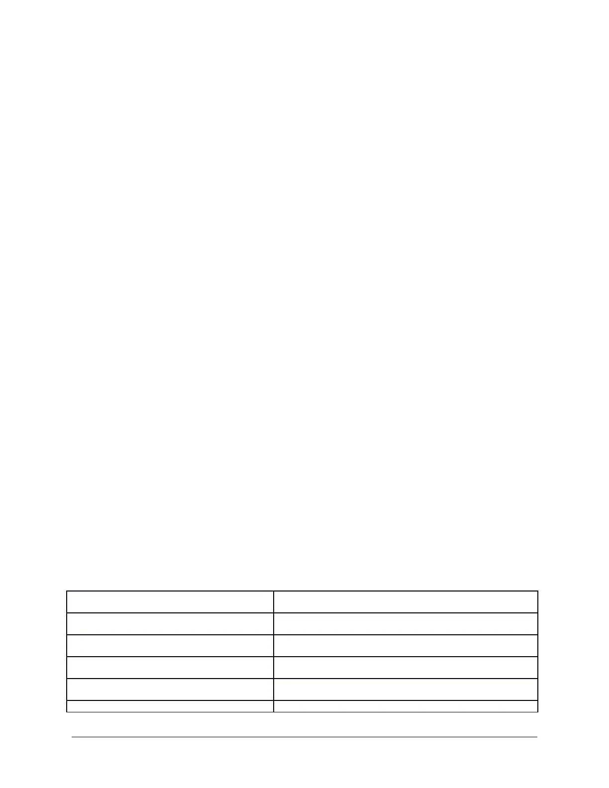
Mike Connector Lug 1 .1VAC
Pin 2 of V1 .02VAC
Pin 6 of V1 10-15VAC
Pin 6 Level Control 10-15VAC
Pin 5 Level Control .5VAC
Pin 9 of V1 .2VAC
SB-100 Service Bulletins Page 162