R110 (***) raises the lower end of the “S” meter zero potentiometer slightly above
ground potential to permit zeroing of the “S” meter in the absence of an input signal.
Ideally, the value would be chosen such that the “S” meter is at S0 in the middle of the
potentiometer travel. If the meter reads above zero and cannot be zeroed, the value of
R110 needs to be reduced, lowering the voltage at the bottom of the potentiometer. If
the meter reads below zero, the value of R11- should be increased.
y.1. “S” Meter vs. AVC Voltage
The “S” Meter reading is controlled by the AVC voltage present at the grid of V3, the 1
st
IF amplifier. As the AVC voltage goes more negative, the “S” meter reading increases.
The following table provides some measured data regarding the relationship between
the AVC voltage and “S” meter reading.
The measurement of the AVC voltage is taken on the RF Driver board at the end of
R415 (1 megohm) that is furthest toward the rear of the chassis. The other end of R415
connects to a 3.3 megohm resistor that comprises a voltage divider that supplies the
AVC voltage to the IF amplifier stages.
In this measurement, the AVC voltage is varied by using the RF Gain control to control
the AVC voltage.
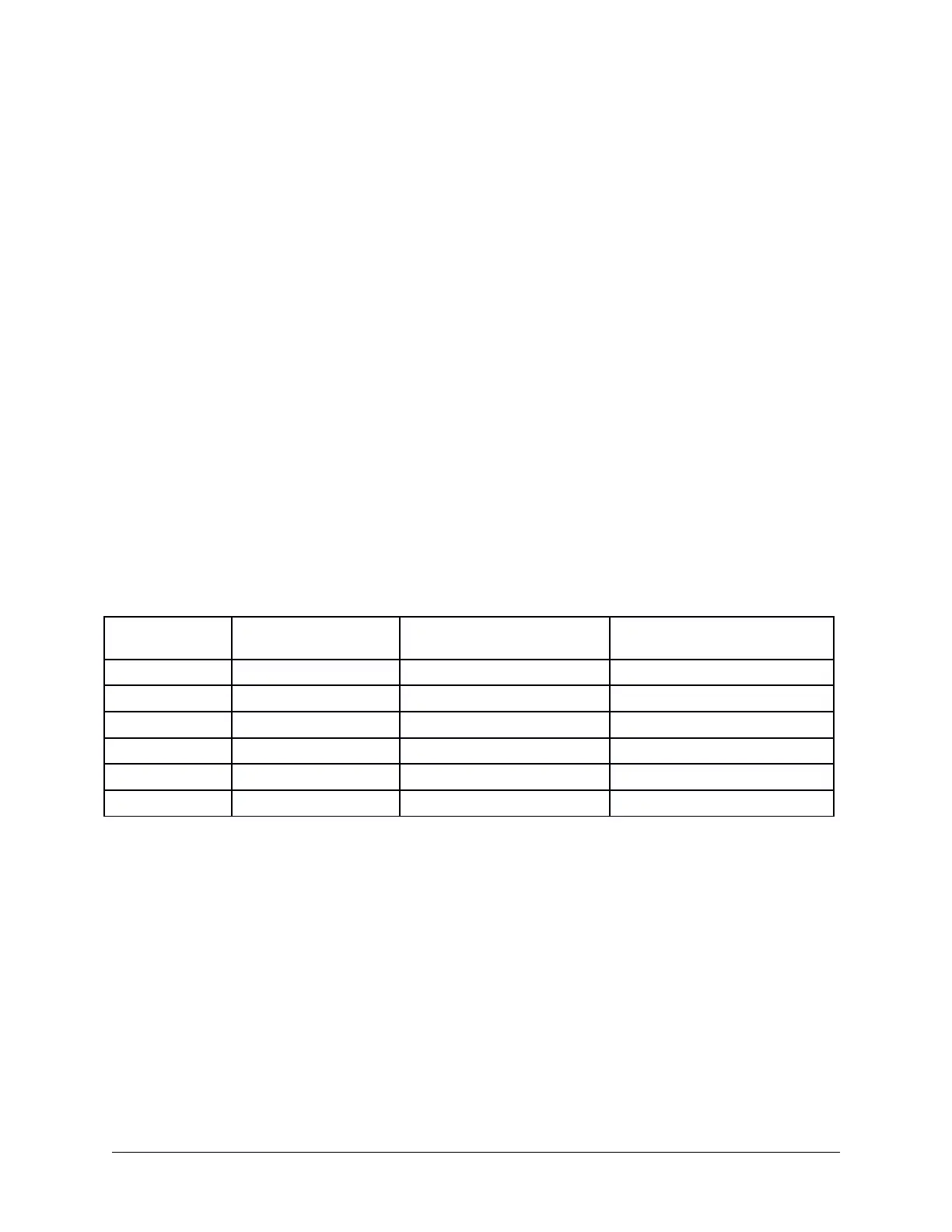
“S” Meter
Reading
AVC Voltage
(measured at R415)
AVC Voltage
(measured at V3 pin 1)
V3 Screen Voltage
(measured at V3 pin 6)
S0 -1.26 vdc -0.88 vdc
S3 -2.43 vdc -1.85 vdc
S6 -3.7 vdc -2.75 vdc
S9 -5.0 vdc -3.7 vdc
S9+20 -6.67 vdc -5.3 vdc
S9+40 -8.88 vdc -7.0 vdc
Table 7. "S" Meter vs. AVC Voltage
The above values can vary from radio to radio and should be viewed only as a guide.
The AVC voltage at V3 pin 1 is provided by a voltage divider on the raw AVC line and
should by approximately 75% on the value measured at R415. If this is not the case, it
may be that one, or both, of the IF amplifier tubes is gassy creating a positive voltage
that bucks the AVC voltage.
Heathkit “S” Meter Circuit Page 62
 Loading...


