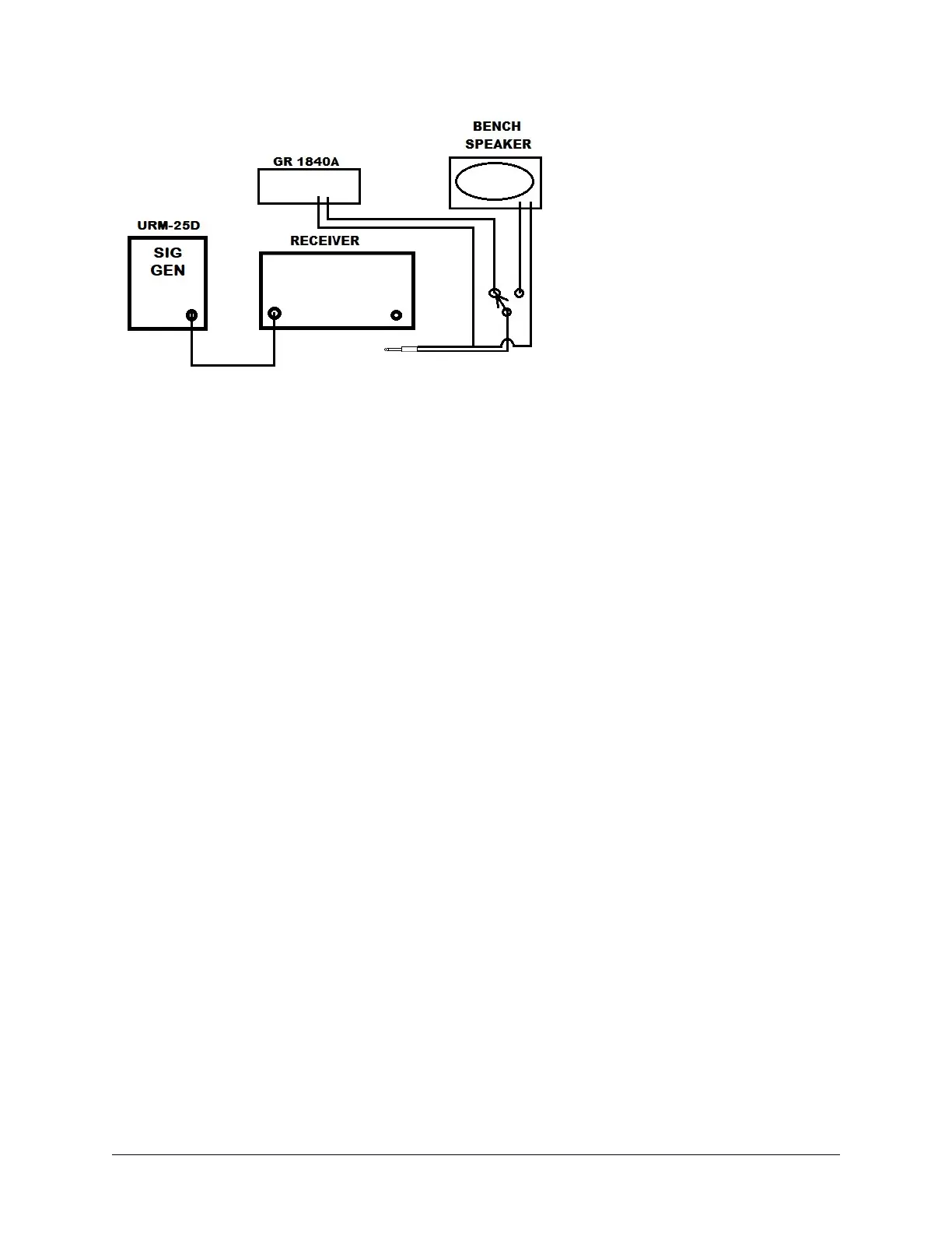
Figure 6. Receiver Test Setup
x.1. Testing
I’ll give you the processes as they relate to the Hallicrafters SR series receivers. You
can figure out the math and apply the process to whatever receiver you wish. ALSO
NOTE THE FOLLOWING APPLIES TO HF BAND RECIEVERS.
x.1.1. Receiver Gain
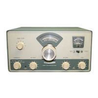
This is pretty straight forward. The gain of the SR-400A for example, is stated: With the
audio and RF gain set to max, a signal at the antenna of 1uv will produce a minimum of
500mw audio output. You can do the math for 1uv into a 50-ohm load producing 500mw
across 3.5ohms and it comes out to 123db gain. This is the minimum acceptable for the
SR-400. With the AF and RF gain both at max the typical gain for the 400A is 139.6db.
If your unit under test states the gain in DB then you have some math you must sort out
and there are many on line calculators that will help you.
x.1.2. (S+N)/N Testing
Once again, I will use the SR-400A. The spec states: Sensitivity -- 1uv or less for 20dB
signal to noise ratio. With 1uv input at the antenna and the receiver properly tuned up,
RF gain at max, AF gain set for 500mw audio output. Disconnect the signal generator
and the noise level should decrease by at least 20 dm. To be totally correct the receiver
should be terminated in 50 ohms when the signal generator is disconnected. I have
found it doesn’t make much difference.
x.1.3. AGC Threshold
The AGC threshold is that point of minimum signal at the antenna where AGC starts to
maintain a constant audio signal level to the speaker. I start at 5uv for all 60’s or later
Testing Gain, S+N/N, AGC Threshold and Figure Of Merit Page 59