ah.4.6. SB-102-6: SB & HW Series Audio Preamplifier & VOX Circuit Trouble
Shooting Guide.
May 23, 1974SB-102 Bulletin No:SSB Transceiver SB-102-6
It is assumed that the basic steps such as making DC voltage measurement, checking
tubes & reviewing the soldering have been completed.
The following information was compiled from the above transceivers in the 80M LSB
position. The mike level control was at the 9:00 o'clock position.
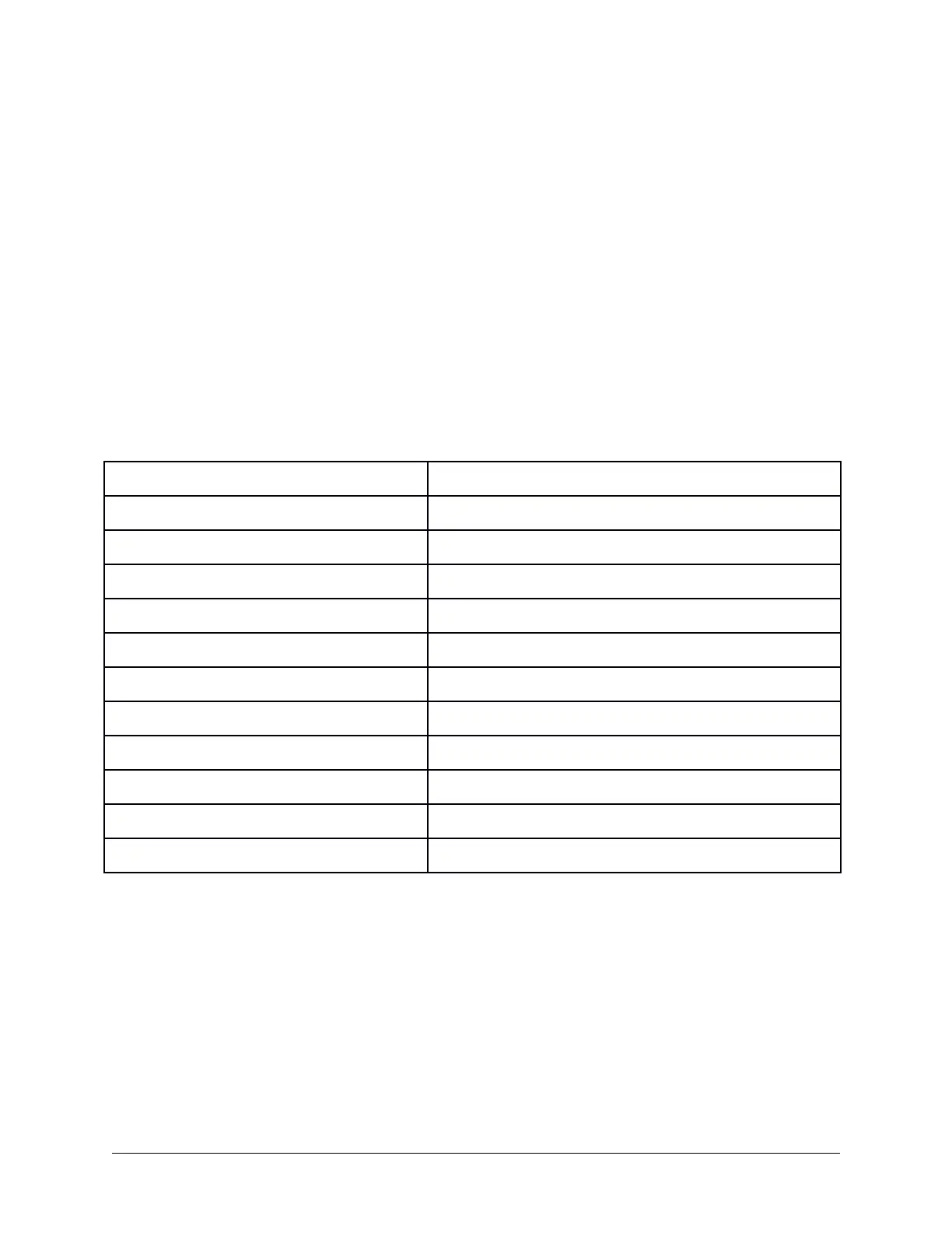
AC signal voltages are listed below. These voltages were measured from the
microphone connector through the VOX circuit. All measurements were made with a
VTVM. A microphone or audio generator for .1V @ 1KHZ can be used as the signal
source.
Mike Connector Lug 1 .1VAC
Pin 2 of V1 .02VAC
Pin 6 of V1 10-15VAC
Pin 6 Level Control 10-15VAC
Pin 5 Level Control .5VAC
Pin 9 of V1 .2VAC
Pin 8 of V1 .1 - .3VAC
Center Arm of VOX Sensitivity Control 5-15VAC
Pin 7 of V17 5-10VAC
Pin 6 of V17 40-50VAC
Junction of C211-D201 40-50VAC
Pin 9 of V12 9-15VAC
By tracing the AC signal from stage to stage the point of trouble can be isolated & steps
taken to correct it.
POSSIBLE TROUBLE AREAS:
- Check each of the shielded cables for a possible open or poorly grounded
shield.- Check for continuity through each of the shielded cables.
- Check for a proper ground at the mike control level.
- - If the frequency response of the audio stage is not within specifications check
the values & installation of C1, C2, C3 & C9.
SB-102 Service Bulletins Page 177

 Loading...


