Page
84
Ee
P=*:v--m=*zdJ
METERING CIRCUITS
C
J
TO CENTER TAP
OF FILAMENT
WINDING
TO-HV
R2
3800
5
W
I
+%A-
A
-
Rf
r)
rn
ZD~
MODE)
-
5
W
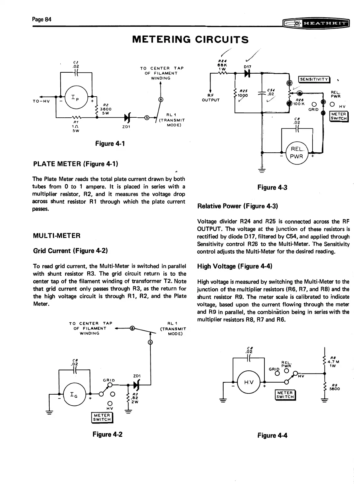
Figure 4-1
PLATE METER (Figure 4-1)
The Plate Meter reads the total plate current drawn by both
tubes from
0 to 1 ampere.
It
is placed in series with a
multiplier resistor, R2, and
it
measures the voltage drop
Figure 4-3
across shunt resistor R1 through which the plate current
passes.
Relative Power (Figure 4-3)
MULTI-METER
Grid Current (Figure 4-2)
Voltage divider R24 and R25
is
connected across the RF
OUTPUT. The voltage at the junction of these resistors
is
rectified by diode 017, filtered by C54, and applied through
Sensitivity control R26 to the Multi-Meter. The Sensitivity
control adjusts the Multi-Meter for the desired reading.
To read grid current, the Multi-Meter is switched in parallel
High Voltage (Figure 4-4)
with shunt resistor R3. The grid circuit return is to the
center tap of the filament winding of transformer T2. Note
High voltage is measured by switching the Multi-Meter to the
that grid current only
passes
through R3, as the return for
junction of the multiplier resistors (R6, R7, and R8) and the
the high voltage circuit is through R1, R2, and the Plate
shunt resistor R9. The meter scale
is
calibrated to indicate
Meter.
voltage,
based
upon the current flowing through the metar
and R9 in parallel, the combinition being in series with the
TO CENTER TAP
OF FILAMENT
WINDING
RL
1
(TRANSMIT
MODE)
multiplier resistors R8, R7 and R6.
Figure 4-2
Figure 4-4