&$=~bj&B
Page
7
1
TUNE-UP
The current and voltage figures given in this section are
CW AND RTTY PROCEDURE
approximations. Actual readings will vary
at
each
installation with such factors as line voltage, exciter drive, Make sure the Amplifier has been installed as described and
and load impedance. illustrated in the "Installation" section. IMPORTANT:
Before proceeding, make sure you have a dummy load (such
The following procedure for tuning the Amplifier should as the Heathkit Cantenna) or an appropriate antenna
take only a few seconds after you go through
it
a
few
times. connected to the Amplifier output.
Note the LOAD control position
so
it
can be preset the next
time a particular band
is
used.
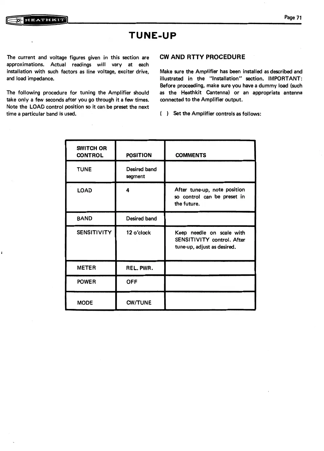
(
Set the Amplifier controls as follows:
SWITCH OR
CONTROL
TUNE
I
LOAD
BAND
SENSITIVITY
METER
POWER
CWITUNE
POSITION
Desired band
segment
4
Desired band
12
o'clock
REL. PWR.
-
COMMENTS
After tune-up, note position
so
control can be preset in
the future.
I
Keep needle on scale with
SENSITIVITY control. After
tune-up, adjust as desired.