Page 24
CHASSIS
CtlASS
IS
BOTTOM
4-40
NUT
Detail
4-1A
FLAT HEAD
d
SCREW
CHASSIS PARTS MOUNTING
Detail
4-1C
Refer to Pictorial 4-1 (fold-out from Page 27) for' the
(
Similarly, mount another phono socket at
X.
following steps.
d
(4
Install 112" rubber grommets
at
Y,
T, AK, and AL.
NOTE: In the following steps,the switch mounting holes are
off center and fit in one position only.
(6
Install a 314" rubber grommet
at
AH.
Refer to Detail 4-lC and mount the DPST rocker
(
4
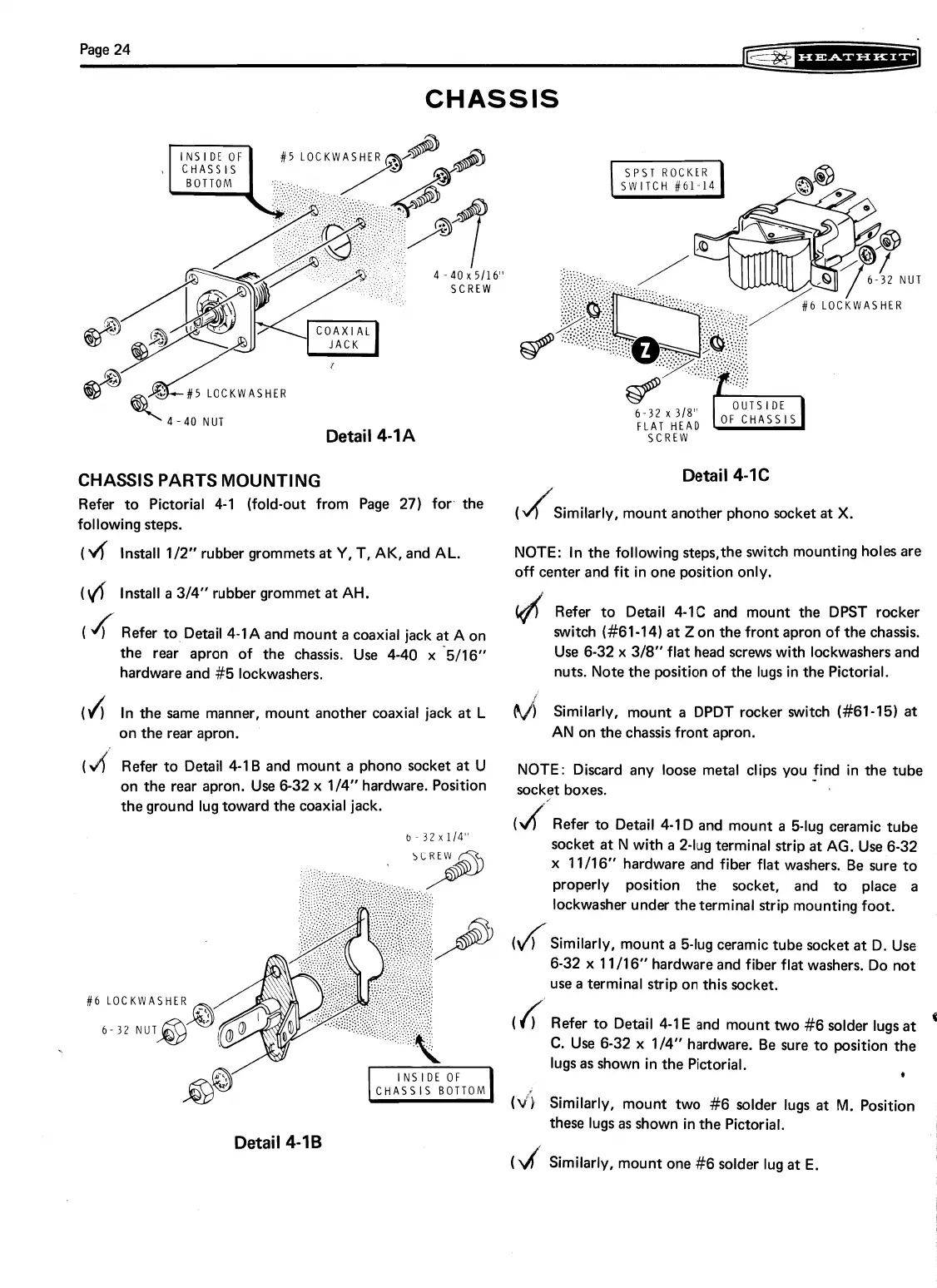
Refer to Detail 4-1A and mount
a
coaxial jack a A on
switch (#61-14) at
Z
on the front apron of the chassis.
the rear apron of the chassis. Use 4-40 x '5116"
Use 6-32 x 318" flat head screws with lockwashers and
hardware and #5 lockwashers.
nuts. Note the position of the lugs in the Pictorial.
(J;
In the same manner, mount another coaxial jack
at
L
Similarly, mount a DPDT rocker switch (#61-15) at
on the rear apron.
AN on the chassis front apron.
(4'
Refer to Detail 4-1 B and mount
a
phono socket
at
u
NOTE: Discard any loose metal clips you !ind in the tube
on the rear apron. Use 6-32 x 114" hardware. Position
sockyt boxes.
the ground lug toward the coaxial jack.
(
Refer to Detail 4-ID and mount
a
5-lug ceramic tube
6
-
32
x
114"
d
socket at
N
with
a
2-lug terminal strip
at
AG. Use 6-32
x 11/16" hardware and fiber flat washers. Be sure to
properly position the socket, and to place a
lockwasher under the terminal strip mounting foot.
(
d
)
Similarly, mount
a
5-lug ceramic tube socket
at
D. Use
6-32 x 1 111 6" hardware and fiber flat washers. Do not
use a terminal strip on this socket.
(6
LOCKWASHE
(
f
Refer to Detail 4-1 E and mount two #6 solder lugs at
4
6-32
NUT
C.
Use 6-32
x
114" hardware. Be sure to position the
lugs as shown in the Pictorial.
*
(dj
Similarly, mount two #6 solder lugs
at
M.
Position
Detail
4-16
these lugs as shown in the Pictorial.
(rlf
Similarly, mount one
#6
solder lug at E.