OPERATION
CONTROLS, CONNECTORS, AND METERS
Refer to Figure
3-1
(fold-out from
Page
68)
for
identification of the front panel controls and a concise
description of the functions of each.
Refer to Figure
3-2
for rear panel connections.
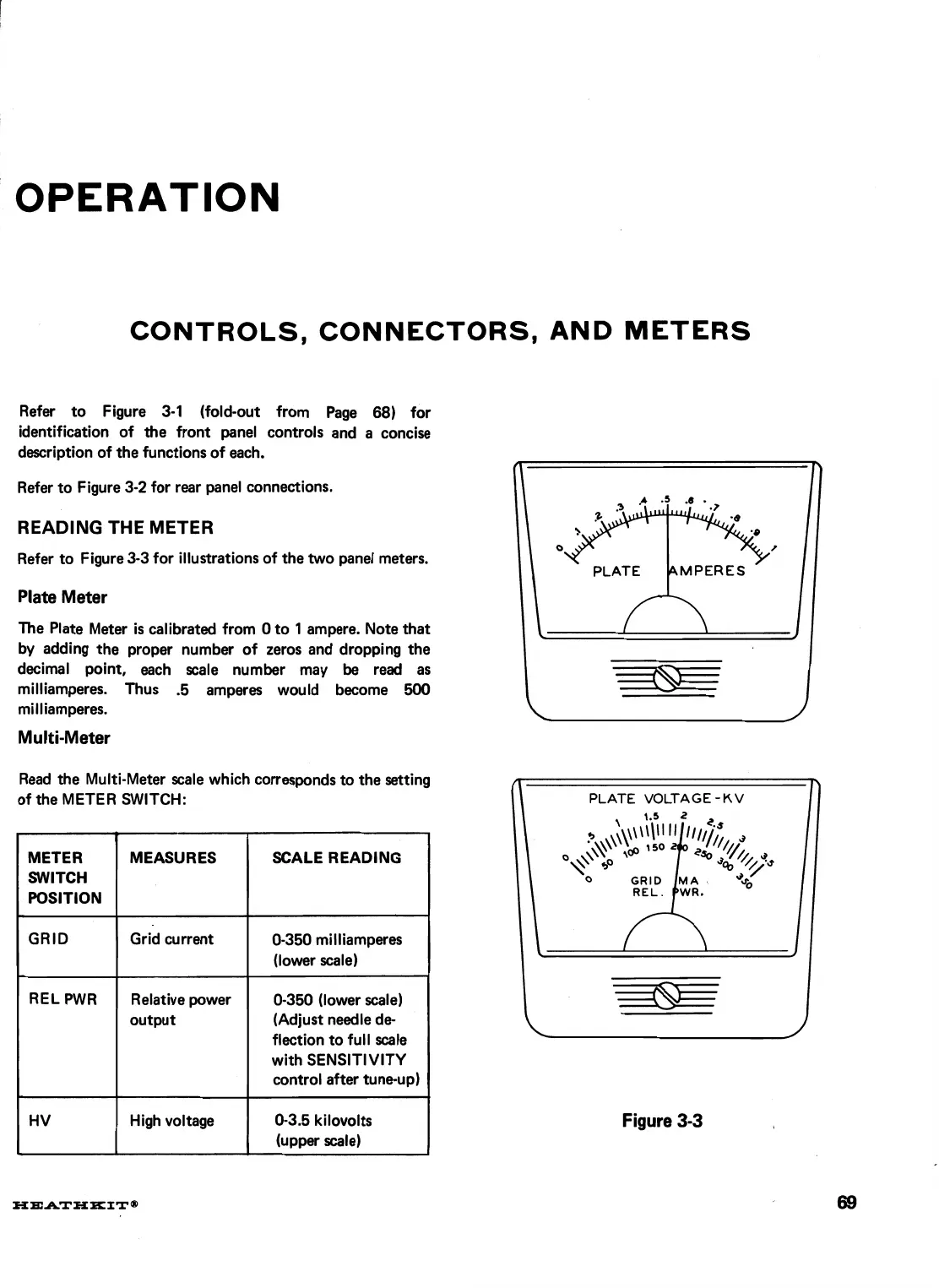
READING THE METER
Refer to Figure
3-3
for illustrations of the two panel meters.
Plate Meter
The Plate Meter is calibrated from
0
to
1
ampere. Note that
by
adding the proper number of zeros and dropping the
decimal point, each scale number may be read as
milliamperes. Thus
.5
amperes would become
500
milliamperes.
Multi-Meter
Read the Multi-Meter scale which corresponds
to
the setting
of the METER SWITCH:
PLATE
VOLTAGE
-
KV
Figure
3-3
SCALE READING
0-350
milliamperes
(lower scale)
0-350
(lower scale)
(Adjust needle
de-
flection to full scale
with SENSITIVITY
control after tune-up)
0-3.5
kilovolts
(upper scale)
METER
SWITCH
POSITION
GRID
REL PWR
HV
-
MEASURES
Grid current
Relative power
output
High voltage