Hints and Kinks
Conducted By David Newkirk, AK7M
Assistant Technical Editor
USING THE SB-220 AMPLIFIER
WITH SOLID-STATE TRANSCEIVERS
The Heathkit SB-220 is one of the most
popular amplifiers ever sold. It was designed
in an era when most amateur equipment was
based on vacuum-tube technology. Because
of this, special care is needed if the SB-220
is to be used with a solid-state transceiver.
The SB-220 goes into the transmit mode
when the hot contact of its rear-panel
ANT
RLY
jack (J1 in Fig 1A) is shorted to
ground, actuating K1, the SB-220 antenna
relay. The open-circuit dc voltage at this
jack is 125; the short-circuit current is
25
mA.
Vacuum-tube-based exciters usually
have no trouble switching power at this
level. Solid-state rigs are a different story.
My
ICOM IC-740 transceiver can't switch
125 V at 25
mA
because the maximum
ratings for its amplifier-control relay con-
tacts are 24 V/1 A dc. Other solid-state
transceivers likely use relays or open-
collector transistors of similar ratings for
amplifier control. The switching problem is
complicated by the fact that the SB-220
antenna-relay solenoid is not shunted by a
spike-suppression diode. The transient
voltage developed by a solenoid's collapsing
magnetic field can exceed the supply voltage.
(If you've ever gotten a poke from relay-
solenoid back EMF, you know that this
voltage is not just theoretical!) With the
24-V rating of the IC-740's control contacts
in mind, a direct amplifier-control connec-
tion between the SB-220 and the IC-740
seemed to invite trouble.
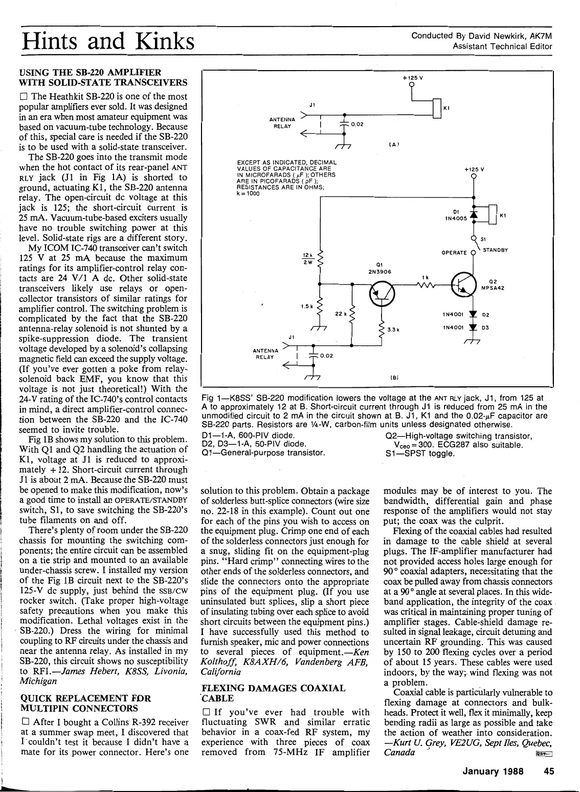
Fig 1B shows my solution to this problem.
With Q1 and 42 handling the actuation of
K1, voltage at J1 is reduced to approxi-
mately
+
12. Short-circuit current through
J1 is about 2
mA.
Because the SB-220 must
be opened to make this modification, now's
a good the to install an
OPERATE/STANDBY
switch, S1, to save switching the SB-220's
tube filaments on and off.
There's plenty of room under the SB-220
chassis for mounting the switching com-
ponents; the entire circuit can be assembled
on a tie strip and mounted to an available
under-chassis screw. I installed my version
of the Fig 1B circuit next to the SB-220's
125-V dc supply, just behind the
SSB/CW
rocker switch. (Take proper high-voltage
safety precautions when you make this
modification. Lethal voltages exist in the
SB-220.) Dress the wiring for minimal
coupling to
RF
circuits under the chassis and
near the antenna relay. As installed in my
SB-220, this circuit shows no susceptibility
to RFI .-James Hebert, K8SS, Livonia,
Michigan
QUICK REPLACEMENT FDR
MULTIPIN CONNECTORS
0
After I bought a Collins R-392 receiver
at a summer swap meet, I discovered that
I'couldn't test it because I didn't have a
mate for its power connector. Here's one
Fig 1-K8SS' SB-220 modification lowers the voltage at the
ANT
RLY
jack, J1, from 125 at
A
to approximately 12 at B. Short-circuit current through J1
is
reduced from
25
mA
in
the
unmodified circuit to 2 mA in the circuit shown at B. J1, K1 and the 0.02-pF capacitor are
SB-220 parts. Resistors are
1/4-W,
carbon-film units unless designated otherwise.
Dl-1-A, 600-PIV diode.
Q2-High-voltage switching transistor,
D2, D3-1-A, 50-PIV diode.
V,,,
=
300. ECG287 also suitable.
Q1-General-purpose transistor. S1-SPST toggle.
Cl25V
ANTENNA
RELAY
>A
..
<+Lo'" CAI
EXCEPT
AS
INDICATED,
DECIMAL
VALUES
OF
CAPACITANCE
ARE
+I25 V
IN
MICROFARADS
(
pF
);
OTHERS
ARE
IN
PICOFARADS
(
pF
);
RESISTANCES
ARE
IN
OHMS;
k=1000
I2
k
-
2
W
at
solution to this problem. Obtain a package
of solderless butt-splice connectors (wire size
no. 22-18 in this example). Count out one
for each of the pins you wish to access on
the equipment plug. Crimp one end of each
of the solderless connectors just enough for
a snug, sliding fit on the equipment-plug
pins. "Hard crimp" connecting wires to the
other ends of the solderless connectors, and
slide the connectors onto the appropriate
pins of the equipment plug. (If you use
uninsulated butt splices, slip a short piece
of insulating tubing over each splice to avoid
short circuits between the equipment pins.)
I
have successfully used this method to
furnish speaker, mic and power connections
to several pieces of equipment.-Ken
Koltho
ff,
K8AXHI6, Vandenberg AFB,
California
I
FLEXING DAMAGES COAXIAL
'CABLE
213906
I
If you've ever had trouble with
fluctuating SWR and similar erratic
behavior in a coax-fed RF system, my
experience with three pieces of coax
removed from 75-MHz IF amplifier
22
1
IN4001
1(r
D2
J
I
ANTENNA
>,
-
I81
modules may be of interest to you. The
bandwidth, differential gain and phase
response of the amplifiers would not stay
put; the coax was the culprit.
Flexing of the coaxial cables had resulted
in damage to the cable shield at several
plugs. The IF-amplifier manufacturer had
not provided access holes large enough for
90"
coaxial adapters, necessitating that the
coax be pulled away from chassis connectors
at
a
90'
angle at several places. In this wide-
band application, the integrity of the coax
was critical in maintaining proper tuning of
amplifier stages. Cable-shield damage re-
sulted in signal leakage, circuit detuning and
uncertain
RF
grounding. This was caused
by 150 to 200 flexing cycles over a period
of about 15 years. These cables were used
indoors, by the way;. wind flexing was not
a problem.
Coaxial cable is parti&larly vulnerable to
flexing damage at connectors and bulk-
heads. Protect it well, flex it minimally, keep
bending radii as large as possible and take
the action of weather into consideration.
-Kurt
U.
Grey,
KE2UG,
Sept Zles, Quebec,
Canada
"
@?3
January
1988
45