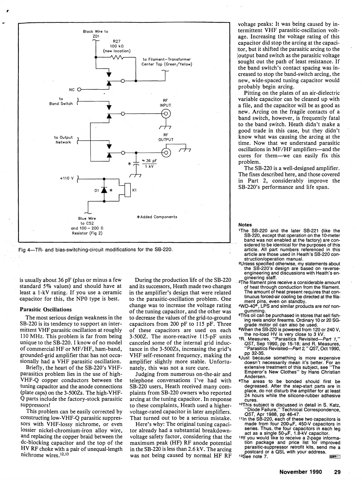
Fig 4-TR- and bias-switching-circuit modifications for the SB-220.
Block W~re to
ZD1
-
R27
100
kn
(new locot~on)
'-
to Filament-Transformer
Center Top
(Green/Yellow)
-
-
NC
0
Band Switch
-
RF
INPUT
+
voltage peaks: It was being caused by in-
termittent VHF parasitic-oscillation volt-
age. Increasing the voltage rating of this
capacitor did stop the arcing at the
capaci-
itor, but it shifted the parasitic arcing to the
'
/output band switch as the parasitic voltage
sought out the path of least resistance. If
the band switch's contact spacing was in-
creased to stop the band-switch arcing, the
new, wide-spaced tuning capacitor would
probably begin arcing.
Pitting on the plates of an air-dielectric
variable capacitor can be cleaned up with
a file, and the capacitor will be as good as
new. Arcing on the fragile contacts of a
band switch, however, is frequently fatal
to the band switch. Heath didn't make a
good trade in this case, but they didn't
know what was causing the arcing at the
time. Now that we understand parasitic
oscillations in
MF/HF amplifiers-and the
cures for them-we can easily fix this
problem.
The SB-220 is a well-designed amplifier.
The fixes described here, and those covered
in Part 2, considerably improve the
SB-220's performance and life span.
to output
Notes
'The SB-220 and the later SB-221 (like the
SB-220, except that operation on the 10-meter
band was not enabled at the factory) are con-
RF
sidered to be identical for the purposes of this
article.
All
part numbers referenced
in
this
article are those used
in
Heath's SB-220 con-
Network
OUTPUT
+I10
v
Blue Wire *Added Components
to
C52
and 100-200
Res~stor
(Fig
2)
structionloperation manual.
2Unless specified otherwise,
my
statements about
the SB-220's design are based on
reverse-
enaineerina and discussions with Heath's en-
gineering Gaff.
is usually about 36 pF (plus or minus a few During the production life of the SB-220
3The
filament
pins
receive
a
considerable
amount
standard 5% values) and should have at
and its successors, Heath made two changes
of heat throuah conduction from the filament.
least a
1-kV rating. If you use a ceramic
in the amplifier's design that were related
The amount
cf
heat present requiresthat con-
capacitor for this, the NPO type is best.
to the parasitic-oscillation problem.
One
:,","/$,,"':$$!
:r$!!,b,"!ected
at
the
fiIaa
change was to increase the voltage rating
4WD-40B, LPS and similar products are not non-
Parasitic Oscillations
of the tuning capacitor, and the other was
gumming.
The most serious design weakness in the to decrease the values of the grid-to-ground
5T~~~~~2a~~1~~~~~~~~~.i62~~~t~~~~~2~:
SB-220 is its tendency to support an inter-
capacitors from
200 pF to 115 pF. Three
grade motor oil can also be used.
mittent VHF parasitic oscillation at roughly of these capacitors are used on each
the SB-220 is powered from
120
or 240
V,
the no-load
I-iy
is vety close to 3 kV.
110 MHz. This problem is far from being
3-5002. The more-reactive 115-pF units
,R.
Measures,
Parasitics
Revisited-Part
,,"
unique to the SB-220. I know of no model
canceled some of the internal grid
induc-
QST,
Sep 1990, pp 15-18; and R. Measures,
of commercial HF or MF/HF, ham-band,
tance in the
3-500Zs, increasing the grid's
Parasitics Revisited-Part2,"
OST.
Oct
1990,
pp 32-35.
grounded-grid amplifier that has not occa-
VHF self-resonant frequency, making the
Uust
because
something
is
more
expensive
sionally had a VHF parasitic oscillation.
amplifier slightly more stable. Unfortu-
doesn't necessarily mean it's better. For an
Briefly, the heart of the SB-220's
VHF-
nately, this was not a sure cure.
extensive treatment of this subject, see "The
parasitics problem lies in the use of high-
Judging from numerous on-the-air and
~~$~~~
New
Clothes"
by
Hans
Christian
VHF-Q copper conductors between the
telephone conversations I've had with
9The areas to be bonded should first be
tuning capacitor and the anode connections
SB-220 users, Heath received many com-
degreased. After the step-start parts are
in
(plate caps) on the 3-5002s. The high-VHF- plaints from SB-220 owners who reported
!$$::
~i~S~{~bsf~~~~~~~~e~~~~~~~
Q parts include the factory-stock parasitic
arcing at the tuning capacitor. In response
cures.
suppressors!
to these complaints, Heath used a higher-
1°T,;is subject is discussed
in
detail
in
S. Katz,
Diode
Failure,".Technical Correspondence,
This problem can be easily corrected by
voltage-rated capacitor in later amplifiers.
OST,
Apr
1988,
pp
46-47,
constructing low-VHF-Q parasitic suppres-
That turned
Out to be a serious mistake.
llln
the SB-220, each df these two capacitors is
sors with
VHF-lossy nichrome, or even Here's why: The original tuning capaci-
made from four 200-iiF, 4504 capacitors
in
lossier nickel-chromium-iron alloy wire, tor already had a substantial breakdown-
z:E
~~~i,~h&-~,
~a~-~~~p~c~~~h
leg
and replacing the copper braid between the voltage safety factor, considering that the
l21f
you would like to receive a 2-page informa-
dc-blocking capacitor and the top of the
maximum peak (HF) RF anode potential
tion
Package and
Price
list for improved
HV
RF
choke with a pair of unequal-length
in the
SB-220 is less than
2.6
kV. The arcing
~~~~~$-~P~~~~~$t~~~~~~b,"ee~d
me
a
nichrome wires.12.1' was not being caused by normal HF RF Issee note
7.
BET3
November
1990
29