Circuit Improvements
for the
Heath
SB-220
Amplifier-Part
2+
Have you made the modifications covered in Part
I?
Here's
-
more-much of which applies to other
3-5002
amplifiers, too.
By
Richard
L.
Measures,
AG6K
6455
La
Cumbre Rd
Somis,
CA
93066
T
he
Heath
SB-220 was well designed,
which is why so many of them are
still in regular use. In Part 1 last
month, I described how to eliminate weak-
nesses in the high-voltage power supply and
other areas to increase the performance and
service life of the SB-220 (and its descen-
dants, the SB-221 and HL-2200).
As
in Part
1,
all
part numbers referred to in the text
and diagrams, unless specified otherwise,
are those
used
by Heath in the SB-220
documentation.
3-5002
Grid
Protection
It's a good idea to replace each grid-to-
ground RF choke (RFC-4 and RFC-5)
with
a
24-
to 30-Q, 1/2-W grid-fuse resistor. In
the event of a parasitic oscillation or some
other serious problem, the grid-fuse resis-
tors open and protect the grids from exces-
sive current. Carbon-fh resistors are good
for this application because they are much
less able to withstand overloads than metal-
oxide-film resistors (or the stock RF
chokes, for that matter). In this applica-
tion, we
want
them to blow up (fail open)
in the event of a grid-current surge.
In order to protect these frangible resis-
tors from
RF
during normal operation, the
total grid-bypass capacitance per tube
socket should be increased to at least
1800 pF.
This
capacitance is necessary if
you use the amplifier on 10 or 15 meters
in a continuous-carrier mode.
Zener-Diode Replacement
One of the more-common casualties
during a
VHF
parasitic oscillation is the
cathode-bias Zener diode. Because cathode
current is the sum of the tube's anode and
grid currents, the cathode Zener diode gets
zapped by the large grid-current pulse that
accompanies a VHF parasitic oscillation.
This is the same current pulse that causes
the vast majority of filament-to-grid shorts
in SB-220 3-500Zs. This pulse also blows
away R3 (the grid-current-meter shunt
resistor), the multimeter movement (if the
multimeter switch is in the grid-current
tPart
1
of this article appeared in
OST,
Nov
1990,
pp
2529.
position when the current pulse
occurs),
the
stock, l-mH grid-to-ground RF chokes,
and the 200-pF mica grid-to-ground capa-
citor~.'~
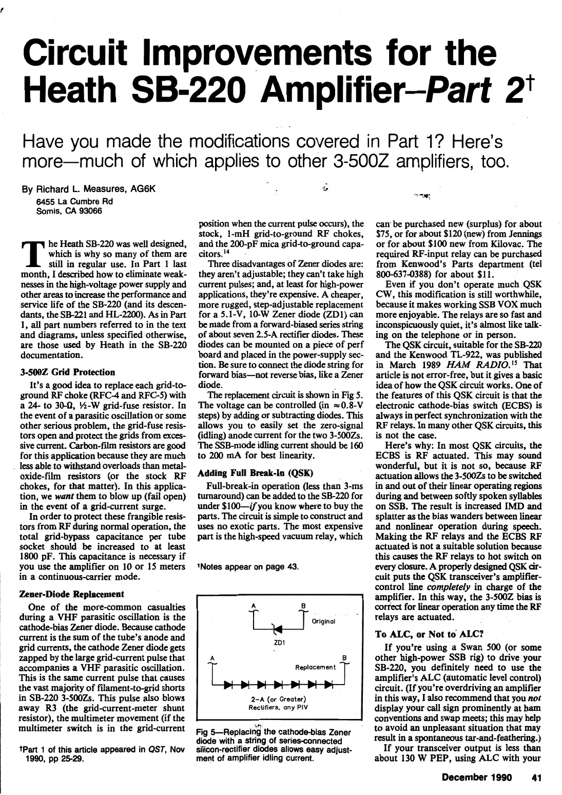
Three disadvantages of Zener diodes are:
they aren't adjustable; they can't take high
current pulses; and, at least for high-power
applications, they're expensive. A cheaper,
more rugged, step-adjustable replacement
for a 5.1-V, 10-W Zener diode (ZD1) can
be made from a forward-biased series string
of about seven 2.5-A rder diodes. These
diodes
can
be mounted on a piece of perf
board and placed
in
the power-supply sec-
tion.
Be
sure to connect the diode string for
forward bias-not reverse bias, like a Zener
diode.
The replacement circuit
is
shown
h
Fig 5.
The voltage can
be
controlled
(in
~0.8-V
steps)
by adding or subtracting diodes.
This
allows you to easily set the zero-signal
(idling) anode current for the two 3-500Zs.
The SSB-mode idling current should
be
160
to 200
mA
for best linearity.
Adding
Fun
Break-In
(QSK)
Full-break-in operation
(less
than 3-ms
turnaround)
can
be added
to
the SB-220 for
under $100-ifyou know where to buy the
parts.
The circuit is simple to construct and
uses
no exotic parts. The most expensive
part
is the high-speed vacuum relay, which
'Notes appear on page
43.
Original
L3
ZD1
-
-
A
2-A
(or Greater)
Rectifiers,
any PIV
Fig 5--Replaci1$ the cathode-bias Zener
diode with a string of seriesconnected
silicon-rectifier diodes allows easy adjust-
ment of amplifier idling current.
can
be purchased new (surplus) for about
$75, or for about $120 (new) from
Jennings
or for about $100 new from Kilovac. The
required RF-input relay
can
be purchased
from Kenwood's Parts department (tel
800-6374388) for about
$11.
Even if you don't operate much QSK
CW,
this modification is still worthwhile,
because it makes working SSB
VOX
much
more enjoyable. The relays are so fast and
inconspicuously quiet, it's almost like
talk-
ing on the telephone or in person.
The QSK circuit, suitable for the SB-220
and the Kenwood TL-922, was published
in March 1989
HAM
That
article is not error-free, but it gives a basic
idea of how the QSK circuit works. One of
the features of this QSK circuit is that the
electronic cathode-bias switch (ECBS) is
always in perfect synchronization with the
RF relays. In many other QSK circuits,
this
is not the case.
Here's why: In most QSK circuits, the
ECBS is RF actuated. This may sound
wonderful, but it is not so,
because
RF
actuation allows the 3-500Zs to be switched
in
and out of their linear operating regions
during and between softly spoken syllables
on SSB. The result is increased IMD and
splatter as the bias wanders between linear
and nonlinear operation during speech.
Making the RF relays and the ECBS RF
actuated is not a suitable solution because
this causes the RF relays to hot switch on
every closure. A properly designed QSK
cir-
cuit puts the QSK transceiver's amplifier-
control line
completely
in charge of the
amplifier. In this way, the 3-5002 bias is
correct for linear operation any time the
RF
relays are actuated.
To
ALC,
or Not to
ALC?
If you're using a Swan 500 (or some
other high-power SSB rig) to drive
your
SB-220, you definitely need to use the
amplifier's ALC (automatic level control)
circuit. (If you're overdriving an amplifier
in this way, I also recommend that you
not
display your
call
sign prominently at ham
conventions and swap meets;
this
may help
to avoid an unpleasant situation that may
result in a spontaneous tar-and-feathering.)
If your transceiver output
is
less than
about 130 W PEP, using ALC with your
I
December
1990
41