SB-220 is of no value, because your rig
can't overdrive the
amplifier.16
Operation on the
12
and 17-Meter Bands
One of the main problems with using
olderdesign, ham-band-only amplifiers on
the 12- and 17-meter bands is choke fires.
Here's what happens: When a high-voltage
RF
choke is operated at or near one of its
series-resonant frequencies, an extremely
high
RF voltage appears across the choke.
This voltage can easily exceed four times
the supply voltage, and can cause the in-
sulation on the choke windings to break
down and ignite. Amplifier manufacturers
are
careful to design RF chokes so that no
resonances occur near the bands on which
the amplifier is designed to operate, but the
SB-220 was designed years before we
acquired the 12- and 17-meter bands at
WARC-79.
To prevent choke fires, all operating
frequencies should be more than 5% away
from any of the choke's series-resonant fre-
quencies. The SB-220 operates well on the
12- and 17-meter bands because, fortu-
nately, its HV RF choke doesn't have any
series resonances below
40
MHz.
If you use a transistor-output transmit-
ter
to drive an SB-220, the amplifier's tuned
input circuits for the 10- and 15-meter
bands should be optimized for this pur-
pose. (More on this later.) The only poten-
tial problem associated with
122 and
17-meter operation with the SB-220 is the
increased current burden on the output
band switch.
Here's why: In order for the amplifier
to tune to the new frequencies without in-
creased output-circuit inductance, the
tuning and loading capacitors must be
adjusted for about 35% more capacitance
than
optimum for the band-switch settings
involved (15 m for 17-m operation, and
10 m for 12-m use). This increases the oper-
ating Q of the output
?r
network by about
18%, which increases the RF-circulating
current in the band-switch contacts by the
same factor. Because power is proportional
to the square of current, the increase in
band-switch-contact dissipation is 1.
1g2,
or 1.3!4-a 39% increase in the power (heat)
dissipated by the band-switch contacts."
This is unlikely to be a problem for nor-
mal SSB operation without speech process-
ing. For higher-duty-cycle operation, the
amplifier should be
switche,d,to the lower-
voltage
CWKUNE
position In order to
reduce the average heat dissipation in the
output-band-switch contacts during oper-
ation on 12 and 17 meters.
Improving Input
SWR
The tuned input circuits (Fig 6) in the
SB-220 typically exhibit a maximum input
SWR of about
1.9:l (referenced to 50 Q
resistive). This is satisfactory when tube-
output radios (and some solid-state rigs,
such as those with internal antenna tuners)
are used to drive the amplifier. Nowadays,
though, transistor-output rigs with
high-
SWR
protection are
used
extensively. Many
transistor-output radios are so particular
that they begin to cut back output when
operating into a reactive load with an
SWR
as low as 1.2:l. Translation: The amplifier
will not receive full drive power unless it
has a very low input SWR. On many
bands, this is the case with stock
SB-220s.
For those bands where this isn't the
case,
fortunately, the input SWR can be easily
improved.
The job of
a
tuned input circuit is more
complicated
than
just matching the input
resistance of the amplifier tubes to 50
0.
Here's why: The instantaneous input resis-
tance of a class-B grounded-grid amplifier
fluctuates wildly during the voltage swings
of the
sinusoidal input signal. When the in-
put cathode voltage swings positive,
the
grounded grid looks negative
with
resped
to the cathode, the tube is completely
cut
off; thus, the input resistance
is
nearly
in-
finite.
During
the negative input-voltage
swing, the grid looks more positive and
a
large current flows in the tube-the input
resistance
is
very low.
For example, when the voltage driving
a pair of
3-500Zs peaks at
-
117 V,
the
anode current is at its peak, the instante
ous anode voltage is swinging to its lowest
point (about
+250
V),
and the total
cathode current is 3.4
A.I8 Thus, the driv-
ing resistance at this point,
R,, is
-
117
V
+
3.4
A
=
34.5 Q and, incredibly, P,,
=
-117
V
x
3.4 A
=
397
W.
Thus, the resistance swings from nearly
infiity
with
positive driving voltage,
all
the
way down to 34.5 Q.19 The drive-power
re-
quirement varies from 0 W to 397 W over
the positive and negative travel of the in-
put signal!
This
is
not
the type of load
that
makes for contented transistor+utput
trans-
ceivers.
During the positive input-voltage swing,
there is virtually no load on the driver,
so
the input circuit must store the drive ener-
gy
until
it is needed the most: during the
negative input-voltage crest. Thus, the
tuned input circuit's job is to act as a
flywheel-like energy-storage system-and
as a matching transformer.
Circuit Q
is
like the inertia of a flywhed.
More Q makes for a better
RF
flywheel,
which does a better job of smoothing the
wild swings in input resistance.
This
results
in a stable, lower input SWR. The trade-
off is that higher Q means less bandwidth.
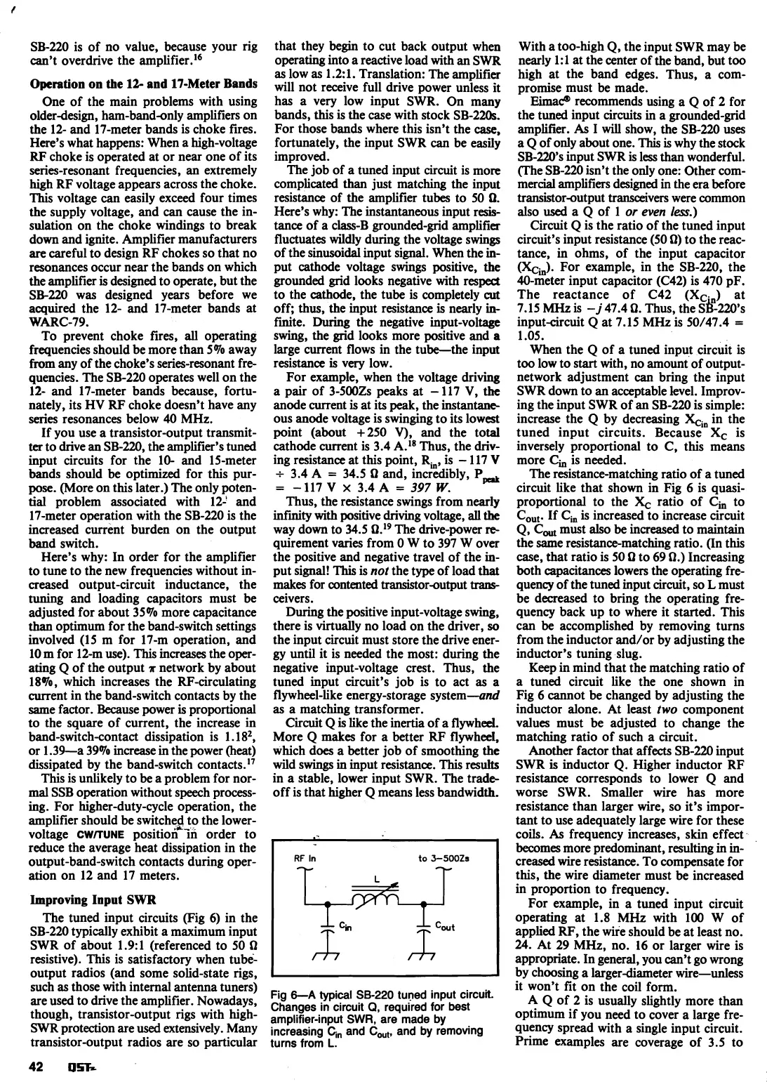
Fig
6-A
typical
SB-220
tuned input circul.
Changes
in
circuit
Q,
required for best
amplifier-input
SWR,
are made
by
increasing
C,,
and
C,,,
and
by
removing
turns from
L.
With a too-high Q, the input SWR may be
nearly
1:l at the center of the band, but too
high at the band edges. Thus, a com-
promise must be made.
Eimac?'
recommends using a
Q
of 2 for
the tuned input circuits in a grounded-grid
amplifier.
As
I
will
show, the SB-220 uses
a Q of only about one.
This
is why the stock
SB-220's input SWR is less than wonderful.
(The SB-220 isn't the only one: Other com-
mercial amplifiers designed in the era before
transistor-output transceivers were common
also
used
a Q of 1
or
even
less.)
Circuit
Q
is the ratio of the tuned input
circuit's input resistance (50
Q) to the reac-
tance, in ohms, of the input capacitor
(XCh).
For example, in the SB-220, the
40-meter input capacitor
(C42) is 470 pF.
The reactance of C42 (Xc.,) at
7.15
MHz
is
-
j
47.4 Q. Thus, the
SB-~U),~
input-circuit Q at 7.15 MHz is 50/47.4
=
1.05.
When the Q of a tuned input circuit is
too low to start with, no amount of
output-
network adjustment can bring the input
SWR down to an acceptable level. Improv-
ing the input SWR of an SB-220 is simple:
increase the
Q
by decreasing
X,,
in the
tuned input circuits. Because
Xc is
inversely proportional to
C,
this means
more
C,
is needed.
The resistance-matching ratio of a tuned
circuit like that shown in Fig
6
is quasi-
proportional to the
X,
ratio of Ci, to
C,. If Cia is increased to increase circuit
Q,
C,
must also be increased to maintain
the same resistance-matching ratio. (In this
case, that ratio is 50
Q to 69 $2.) Increasing
both capacitances lowers the operating fre-
quency of the tuned input circuit,
so
L
must
be decreased to bring the operating fre-
quency back up to where it started. This
can be accomplished by removing turns
from the inductor and/or by adjusting the
inductor's tuning slug.
Keep
in
mind that the matching ratio of
a tuned circuit like the one shown in
Fig
6
cannot be changed by adjusting the
inductor alone. At least
two
component
values must be adjusted to change the
matching ratio of such a circuit.
Another factor that affects SB-220 input
SWR is inductor Q. Higher inductor
RF
resistance corresponds to lower
Q
and
worse SWR. Smaller wire has more
resistance than larger wire, so it's impor-
tant to use adequately large wire for these
coils.
As
frequency increases, skin effect
becomes more predominant, resulting in in-
creased wire resistance. To compensate for
this, the wire diameter must be increased
in proportion to frequency.
For example, in a tuned input circuit
operating at 1.8 MHz with 100
W
of
applied RF, the wire should be at least no.
24.
At 29
MHz,
no.
16
or larger wire is
appropriate. In general, you can't go wrong
by choosing a larger-diameter wire-unless
it won't fit on the coil form.
A
Q
of 2 is usually slightly more than
optimum if you need to cover a large fre-
quency spread with a single input circuit.
Prime examples are coverage of 3.5 to
 Loading...


