4
MHz and 18 to 21.5 MHz
(so
that the
15-meter tuned input circuit
also
covers the
17-meter band). In these cases, a
Q
of
about 1.5 should be used. This
also
applies
to a 10-meter tuned input circuit if the am-
plifier will be used on the 12-meter band.
A
Q
of 1.5 corresponds to a reactance of
about 33.3
f2
(Xc
=
50 Wl.5
=
33.3
Q)
for
G.
At 3.7? MHz, this requires a
1275-pF capacit~r.~ (The nearest standard
value is 1300 pF.) Of course, capacitors can
be paralleled to amve at the desired C.
Measuring amplifier SWR is a very vague
science. For example, different SWR
meters give different readings in the same
circuit! Changing the length of coax
between the SWR meter and the amplifier
can also change the indicated SWR.
Another complication is that modern
transistor-output transceivers, in order to
maintain clean output signals, generally
use
a set of switched, 1.5-octave output filters.
At the extremes of such a filter's passband,
such
as
at 29 MHz, the filter
can
introduce
reactance into the transmission line. This
reactance can cause some peculiar results
when you're trying to optimize the SWR
of an amplifier's tuned input circuits.
For those who
can
do so, the easiest way
to avoid this problem is to use a tube-type
exciter when optimizing the SB-220 input
circuits. The exciter must be tuned for
maximum power into a 50-0 termination,
and then should not be retuned during
adjustment of the input network's induc-
tance and C,. Retuning the exciter may
introduce a reactance that will affect the
indicated SWR.
If the tuned input circuit's
Q
has been
increased by increasing
Ci,
and decreasing
L.
Cout
will
also
need to be increased. The
easiest way to find the new (higher) opti-
mum value for
c,,
is by inserting a trim-
mer in parallel with the stock
Gout.
Then,
with the maximum peak drive power
applied, alternately adjust
L
and C,,, for
the best match at the center of the band.
Gout
can
then
be
removed, its capacitance
measured, and a fixed capacitor of that
value permanently installed in its place.
Adjusting the amplifier's tuned input
cir-
cuits is much easier with the front panel
removed, but the meter leads need to be
lengthened to facilitate
this.
Also,
a chassis-
ground wire must be added between the
panel and the amplifier chassis so that the
multimeter
will
function when the panel is
separated from the rest of the amplifier.
If the amplifier
is
driven with a continu-
ous carrier, considerable stress is placed on
the HV power supply, and the
RF
compart-
ment becomes very hot. This stress
can
be
reduced if the driver
is
set
to the
CW
mode
and keyed with a string of 50- to @WPM
dots. The ampmer's current-meter readings
should be approximately doubled to deter-
mine the
actual
current (meter inertia affects.
the readings, though, so
this
technique can't
be used for exact measurements).
It's very important to avoid contacting
the nearby
HV
fd-through insulator while
you 're adjusting the input networks.
Doing
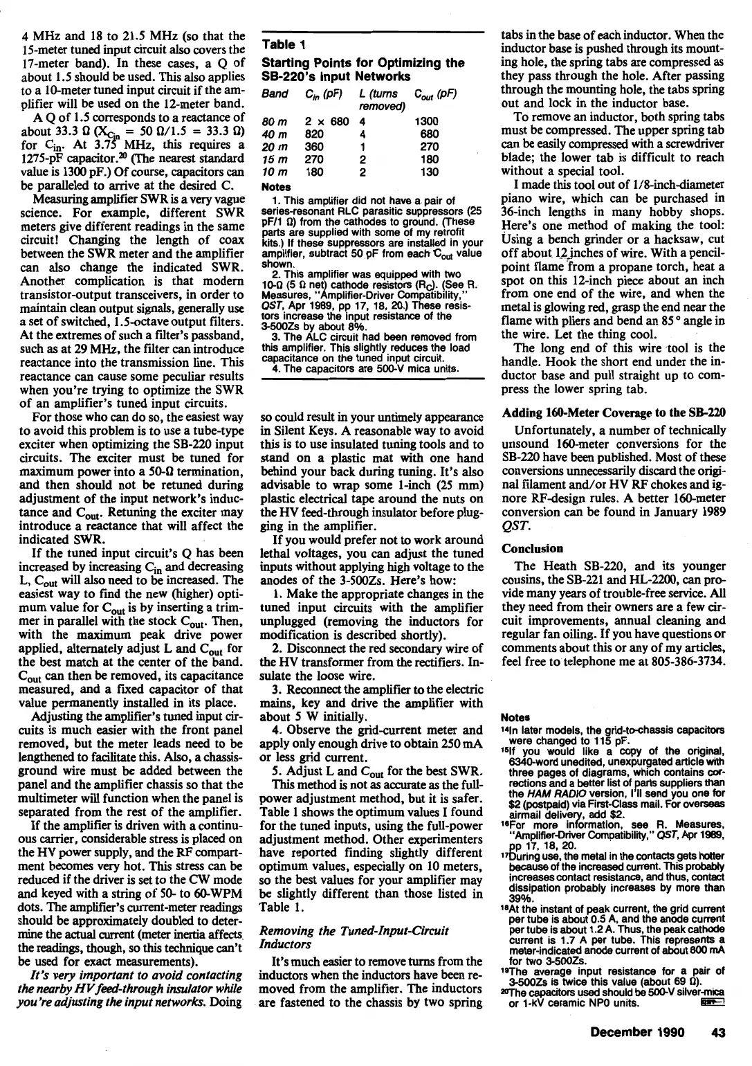
Table
1
Starting Points for Optimizing the
SB-220's Input Networks
Band
Ch
(pF)
L
(turns
C,
(pF)
removed)
80m 2x680
4
1300
40
m
820
4
680
20
m
360
1 270
15m 270 2 180
10m 180 2 130
Notes
1. This amplifier did not have a pair of
series-resonant RLC parasitic suppressors (25
pF11 0) from the cathodes to ground. (These
parts are supplied with some of my retrofit
kits.) If these suppressors are instabd in your
amplifier, subtract 50
pF
from eachC,, value
shown.
2.
This amplifier was equipped with two
10-n
(5
n
net cathode resistors (Rd. (See R.
Measures, knplifier-Driver Compatibility."
QST,
Apr 1989, pp 17, 18,
20.)
These resis-
tors increase the input resistance of the
3-5003 by about 8%.
3. The ALC circuit had been remwed from
this amplifier. This slightly reduces the load
capacitance on the tuned input circuit.
4.
The capacitors are
5004
mica units.
so
could result in your untimely appearance
in Silent Keys. A reasonable way to avoid
this is to use insulated tuning tools and to
stand on a plastic mat with one hand
behind your back during tuning. It's also
advisable to wrap some 1-inch (25 mm)
plastic electrical tape around the nuts on
the HV feed-through insulator before plug-
ging in the amplifier.
If you would prefer not to work around
lethal voltages, you
can
adjust the tuned
inputs without applying high voltage to the
anodes of the 3-500Zs. Here's how:
1. Make the appropriate changes in the
tuned input circuits with the amplifier
unplugged (removing the inductors for
modification is described shortly).
2. Disconnect the red secondary wire of
the
HV
transformer from the rectifiers. In-
sulate the loose wire.
3. Reconnect the ampMer
to
the electric
mains, key and drive the amplifier with
about
5
W initially.
4.
Observe the gridcurrent meter and
apply only enough drive to obtain 250
mA
or less grid current.
5.
Adjust L and C,,, for the best SWR.
This
method
is
not as
accurate
as the full-
power adjustment method, but it is safer.
Table 1 shows the optimum values I found
for the tuned inputs, using the full-power
adjustment method. Other experimenters
have reported finding slightly different
optimum values, especially on 10 meters,
so the best values for your amplifier may
be slightly different than those listed in
Table
1.
Removing the Tuned-Input-Circuit
Inductors
It's much easier to remove
turns
from the
inductors when the inductors have
been
re-
moved from the amplifier. The inductors
are fastened to the chassis by two spring
tabs in the base of each inductor. When the
inductor base is pushed through its mount-
ing hole, the spring tabs are compressed as
they pass through the hole. After passing
through the mounting hole, the tabs spring
out and lock in the inductor base.
To remove an inductor, both spring tabs
must be compressed. The upper spring tab
can
be easily compressed with a screwdriver
blade; the lower tab is difficult to reach
without a special tool.
I made
this
tool out of 1/8-inchdiameter
piano wire, which can be purchased in
36-inch lengths in many hobby shops.
Here's one method of making the tool:
Using a bench grinder or a hacksaw, cut
off about 12jnches of wire. With a pencil-
point flame from a propane torch, heat a
spot on this 12-inch piece about an inch
from one end of the wire, and when the
metal
is
glowing red, grasp the end near the
flame with pliers and bend an 85
"
angle in
the wire. Let the thing cool.
The long end of this wire .tool is the
handle. Hook the short end under the in-
ductor base and pull straight up to com-
press the lower spring tab.
Adding 160-Meter Coverage to the
SB-220
Unfortunately, a number of technically
unsound lameter conversions for the
SB-220 have
been
published. Most of
these
conversions unnecessarily discard the origi-
nal filament and/or HV
RJ?
chokes and ig-
nore RFdesign rules. A better 160-meter
conversion
can
be found in January 1989
QST.
Conclusion
The Heath SB-220, and its younger
cousins,
the SB-221 and
HL-2200,
can
pro-
vide many years of trouble-free service.
All
they need from their owners are a few
cir-
cuit improvements, annual cleaning and
regular fan oiling. If you have questions or
comments about this or any of my articles,
feel free to telephone me at 805-386-3734.
Notes
l4ln later models, the grid-t&assis
capacitors
were changed to 115 pF.
lslf you would like a copy of
the
origi*,
6340-word unedited, unexpurgated artlcle
lmth
three pages of diagrams, which contalns
ax-
rections and a better list of
parts
suppliers
than
the
HAM
RADIO
version, I II send you one for
$2
(postpaid) via First-Class mail. For werseas
airmail delive add
$2.
18For more inrdrrnation, see
R.
Measures.
"Amplifier-Driver Compatibility."
W.
Apr
1969.
17g!2?.9
::.%
metal in the
Antacts
gets
hotter
because of the increased current. This probably
increases contact resistance,
and
thus, contact
dissipation probably increases by more than
39%.
18At the instant of peak current, the grid cunent
per tube is about
0.5
A,
and the anode cumt
per tube is about 1.2 A. Thus, the
peak
cathode
current is 1.7 A per tube. This represents a
meter-indicated anode current of about
800
mA
for two 3-5003.
**The average input resistance for a pair of
3-500Zs is twice this value (about
69
n).
The capacitors used should be
WJV
silver-mica
or
1-kV
ceramic NPO units.
I0.r-l
December 1990
43
 Loading...


