Page 19
/
COUPLER
SHAFT
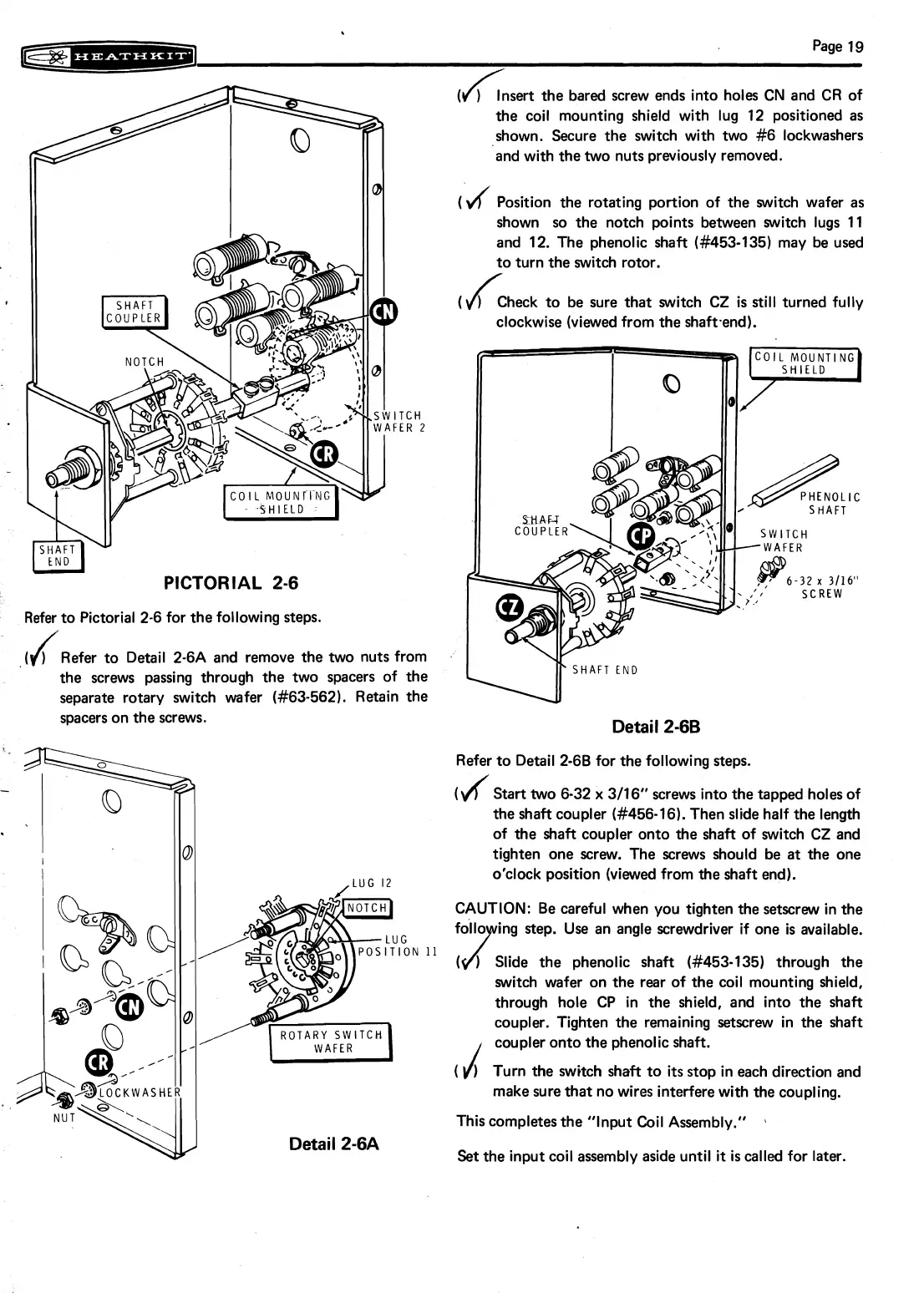
PICTORIAL 2-6
Refer to Pictorial 2-6 for the following steps.
the screws passing through the two spacers of the
separate rotary switch wafer
(#63-562). Retain the
spacers on the screws.
Detail
2-6A
(h
Insert the bared screw ends into holes CN and CR of
the coil mounting shield with lug 12 positioned
as
shown. Secure the switch with two #6 lockwashers
and with the two nuts previously removed.
(V/
Position the rotating portion of the switch wafer as
shown so the notch points between switch lugs 11
and 12. The phenolic shaft
(#453-135) may be used
to turn the switch rotor.
(
/
)
Check to be sure that switch CZ is
still
turned fully
clockwise (viewed from the
shaftend).
w
SHAFT END
Detail
2-66
Refer to Detail 2-68 for the following steps.
(I*f
Stan two 6-32
x
3/16'' screws into the tapped holes of
the shaft coupler
(#456-16). Then slide half the length
of the shaft coupler onto the shaft of switch
CZ and
tighten one screw. The screws should be at the one
o'clock position (viewed from the shaft end).
CAUTION: Be careful when you tighten the setscrew in the
ftdlo ing step. Use an angle screwdriver if one
is
available.
(
/
)
Slide the phenolic shaft (#453-135) through the
switch wafer on the rear of the coil mounting shield,
through hole CP in the shield, and into the shaft
coupler. Tighten the remaining setscrew in the shaft
J
coupler onto the phenolic shaft.
(
1
Turn the switch shaft to
its
stop in each direction and
make sure that no wires interfere with the coupling.
This completes the "Input Coil Assemblv."
Set the input coil assembly aside until
it
is
called for later.