Page 13
Detail 1D
6-32XSV
SCREW
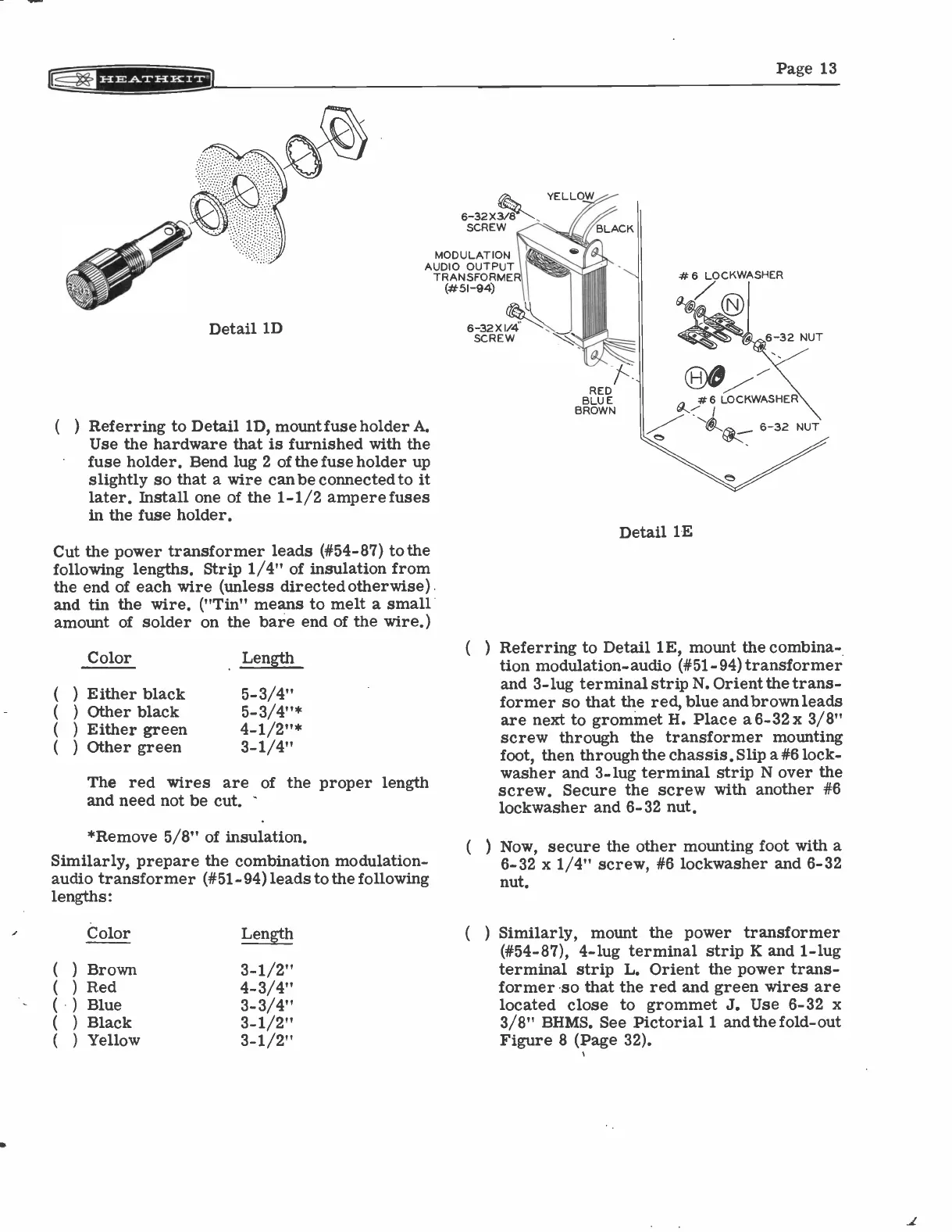
MODULATION
AUDIO OUTPUT
TRANSFORMER
(#51-94)
( ) Referring to Detail 1D, mount fuse holder A.
Use the hardware that is furnished with the
fuse holder. Bend lug 2 of the fuse holder up
slightly so that a wire can be connected to it
later. Install one of the 1-1/2 ampere fuses
in the fuse holder.
Cut the power transformer leads (#54-87) to the
following lengths. Strip 1/4" of insulation from
the end of each wire (unless directed otherwise)
and tin the wire. ("Tin" means to melt a small
amount of solder on the bare end of the wire.)
Color Length
( ) Either black
5-3/4"
( ) Other black 5-3/4"*
( ) Either green 4-1/2"*
(
) Other green
3-1/4"
The red wires are of the proper length
and need not be cut.
*Remove 5/8" of insulation.
Similarly, prepare the combination modulation -
audio transformer (#51-94) leads to the following
lengths:
Color Length
( ) Brown
3-1/2"
( ) Red
4-3/4"
(
) Blue
3-3/4"
( ) Black
3-1/2"
(
) Yellow
3-1/2"
6-32X V4
SCREW
YELLOW
RED
BLUE
BROWN
*6 LOCKWASHER
6-32 NUT
*6 LOCKWASHER
(
4L
Detail lE
6-32 NUT
Referring to Detail 1E, mount the combina-
tion modulation- audio (#51-94) transformer
and 3 -lug terminal strip N. Orient the trans-
former so that the red, blue andbrown leads
are next to grommet H. Place a 6-32 x 3/8"
screw through the transformer mounting
foot, then through the chassis. Slip a #6 lock -
washer and 3 -lug terminal strip N over the
screw. Secure the screw with another #6
lockwasher and 6-32 nut.
Now, secure the other mounting foot with a
6-32 x 1/4" screw, #6 lockwasher and 6-32
nut.
(
) Similarly, mount the power transformer
(#54-87), 4 -lug terminal strip K and 1 -lug
terminal strip L. Orient the power trans-
former so that the red and green wires are
located close to grommet J. Use 6-32 x
3/8" BHMS. See Pictorial 1 and the fold -out
Figure 8 (Page 32).