Page 14
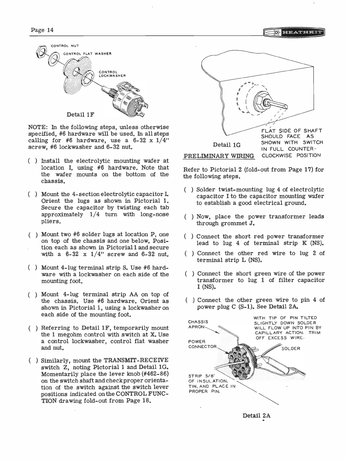
CONTROL NUT
CONTROL FLAT WASHER
CONTROL
LOCKWASHER
Detail 1F
NOTE: In the following steps, unless otherwise
specified, #6 hardware will be used. In all steps
calling for #6 hardware, use a 6-32 x 1/4"
screw, #6 lockwasher and 6-32 nut.
(
Install the electrolytic mounting wafer at
location I,
using #6 hardware. Note that
the
wafer mounts on the bottom of the
chassis.
Mount the 4 -section electrolytic capacitor L
Orient the lugs as shown in Pictorial 1.
Secure the capacitor by twisting each tab
approximately 1/4
turn with long -nose
pliers.
Mount two #6 solder lugs at location P, one
on top of the chassis and one below. Posi-
tion each as shown in Pictorial 1 and secure
with a 6-32 x 1/4" screw and 6-32 nut.
Mount 4 -lug terminal strip S. Use #6 hard-
ware with a lockwasher on each side of the
mounting foot.
Mount 4 -lug terminal strip AA on top of
the chassis. Use #6 hardware. Orient as
shown in Pictorial 1, using a lockwasher on
each side of the mounting foot.
Referring to Detail 1F, temporarily mount
the 1 megohm control with switch at X. Use
a control lockwasher, control flat washer
and nut.
) Similarly, mount the TRANSMIT -RECEIVE
switch Z, noting Pictorial 1 and Detail 1G.
Momentarily place the lever knob (#462-86)
on the switch shaft and check proper orienta-
tion of the switch against the switch lever
positions indicated on the CONTROL FUNC-
TION drawing fold -out from Page 18.
Detail 1G
FLAT SIDE OF SHAFT
SHOULD FACE AS
SHOWN WITH SWITCH
IN FULL COUNTER -
PRELIMINARY WIRING
CLOCKWISE POSITION
Refer to Pictorial 2 (fold -out from Page 17) for
the following steps.
(
) Solder twist -mounting lug 4 of electrolytic
capacitor I to the capacitor mounting wafer
to establish a good electrical ground.
( )
Now, place the power transformer leads
through grommet J.
Connect the short red power transformer
lead to lug 4 of terminal strip K (NS).
Connect the other red wire to lug 2 of
terminal strip L (NS).
Connect the short green wire of the power
transformer to lug
1 of filter capacitor
I (NS).
(
) Connect the other green wire to pin 4 of
power plug C (S-1). See Detail 2A.
CHASSIS
APRON
POWER
CONNECTOR
STRIP 5/8"
OF INSULATION,
TIN, AND PLACE IN
PROPER PIN.
WITH TIP OF PIN TILTED
SLIGHTLY DOWN SOLDER
WILL FLOW UP INTO PIN BY
CAPILLARY ACTION. TRIM
OFF EXCESS WIRE.
Detail 2A
SOLDER