Page 19
C 1 1. Connect a 10 p. pi tubular ceramic capa-
citor from lug 1 of coil CE (NS) to lug 7 of
tube socket V4 (S-2).
Connect a very short length of stripped
hookup wire from lug 1 of coil CE (S-2)
to lug 3 of tube socket V4 (S-1). Be sure
that it
does not short to lug 2 of V4.
Mount the oscillator coil (#40-186) CF.
Connect a 3" length of hookup wire from
lug 2 of coil CD (NS) to lug 2 of coil CF
(NS).
Connect a 4-3/4" length of hookup wire
from lug 2 of coil CD (S-4) to lug 2 of
switch Z (S-2).
C4. Connect a .001 mid disc ceramic ca-
pacitor from lug 2 of coil CF (NS) to the
ground lug nearest lug 8 of tube socket V5
(S-1).
R2. Connect a 22 102 (red -red -orange) 1
watt resistor from lug 2 crystal socket
M (S-2) to lug 2 of coil CF (NS).
C5. Connect a 10 µpi tubular ceramic ca-
pacitor between lugs 1 (NS) and 2 (S-4) of
coil CF.
Connect a length of stripped hookup wire
from lug 1 of coil CF (S-2) to lug 9 of tube
socket V5 (NS).
C6. Connect a 50 1.01f silver mica capacitor
between lugs 2
(S-2) and 9 (S-2) of tube
socket V5.
Connect a length of heavy bare wire from
lug 1 of coil CD (S-1) to lug 3 of tube socket
V5 (S-2).
C7. Connect a .001 p.fd disc ceramic capa-
citor from lug 4 of tube socket V5 (S-2) to
the center post of V5 (NS).
C2. Connect a .001 pid disc ceramic capa-
citor from lug 5 (5-2) to the center lug of
V5 (S-4).
) Install the .001 !Ad feed -through capacitor
T. Use the nut furnished with the capacitor.
Do not overtighten this capacitor since you
may crack the insulating material. See
Detail 4B.
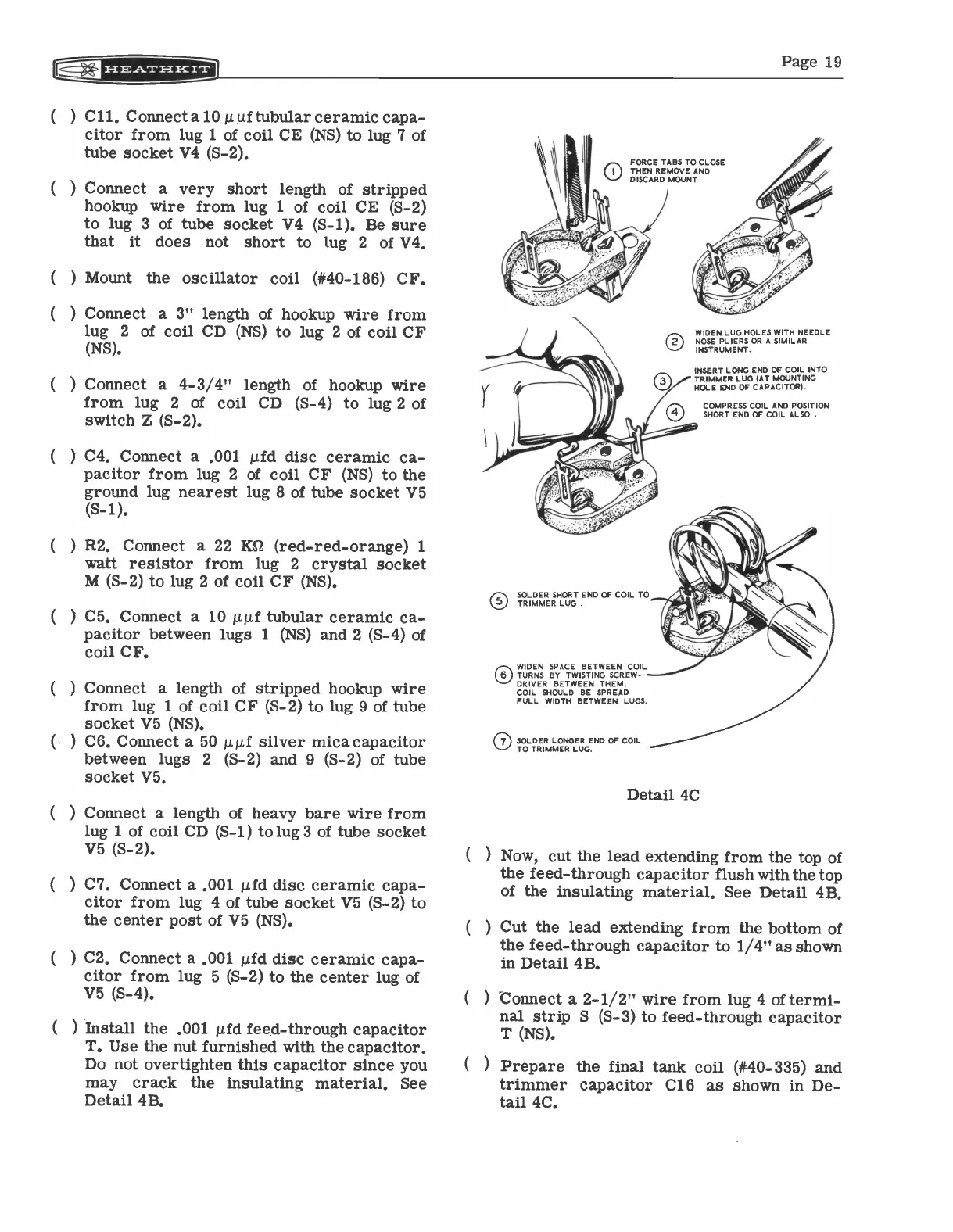
FORCE TABS TO CLOSE
THEN REMOVE AND
DISCARD MOUNT
O
WIDEN LUG HOLES WITH NEEDLE
NOSE PLIERS OR A SIMILAR
INSTRUMENT.
INSERT LONG END OF COIL INTO
TRIMMER LUG (AT MOUNTING
HOLE END OF CAPACITOR).
COMPRESS COIL AND POSITION
SHORT END OF COIL ALSO .
®SOLDER SHORT END OF COIL TO
TRIMMER LUG .
01
WIDEN SPACE BETWEEN COIL
TURNS BY TWISTING SCREW-
DRIVER BETWEEN THEM.
COIL SHOULD BE SPREAD
FULL WIDTH BETWEEN LUGS.
0 SOLDER LONGER END OF COIL
TO TRIMMER LUG.
Detail 4C
(
) Now, cut the lead extending from the top of
the feed -through capacitor flush with the top
of the insulating material. See Detail 4B.
(
) Cut the lead extending from the bottom of
the feed -through capacitor to 1/4" as shown
in Detail 4B.
(
) Connect a 2-1/2" wire from lug 4 of termi-
nal strip S (S-3) to feed -through capacitor
T (NS).
(
) Prepare the final tank coil (#40-335)
and
trimmer capacitor C16 as shown in De-
tail 4C.