Page 23
(
) C41. Connect a .001 pld disc ceramic ca-
pacitor between lugs 2
(NS) and 3 (S-2)
of tube socket Vl.
(
) C36. Connect a .001 p.fd disc ceramic ca-
pacitor from lug 5 of tube socket V1 (S-2)
to lug 2 of terminal strip R (NS).
(
) C43. Connect a .001 pfd disc ceramic
ca-
pacitor between lugs 2 (S-4) and 3 (S-4) of
terminal strip R.
(
) C35. Connect a .01 p.fd disc ceramic ca-
pacitor from lug 6 of tube socket V1 (S-2)
to lug 1 of tube socket V2 (S-1).
(
) R22. Place a 15/16" length of sleeving over
each lead of a 470 Ksz (yellow -violet -yellow)
resistor and connect from lug 7 of tube sock-
et V1 (S-2) to lug 2 of control X (S-1).
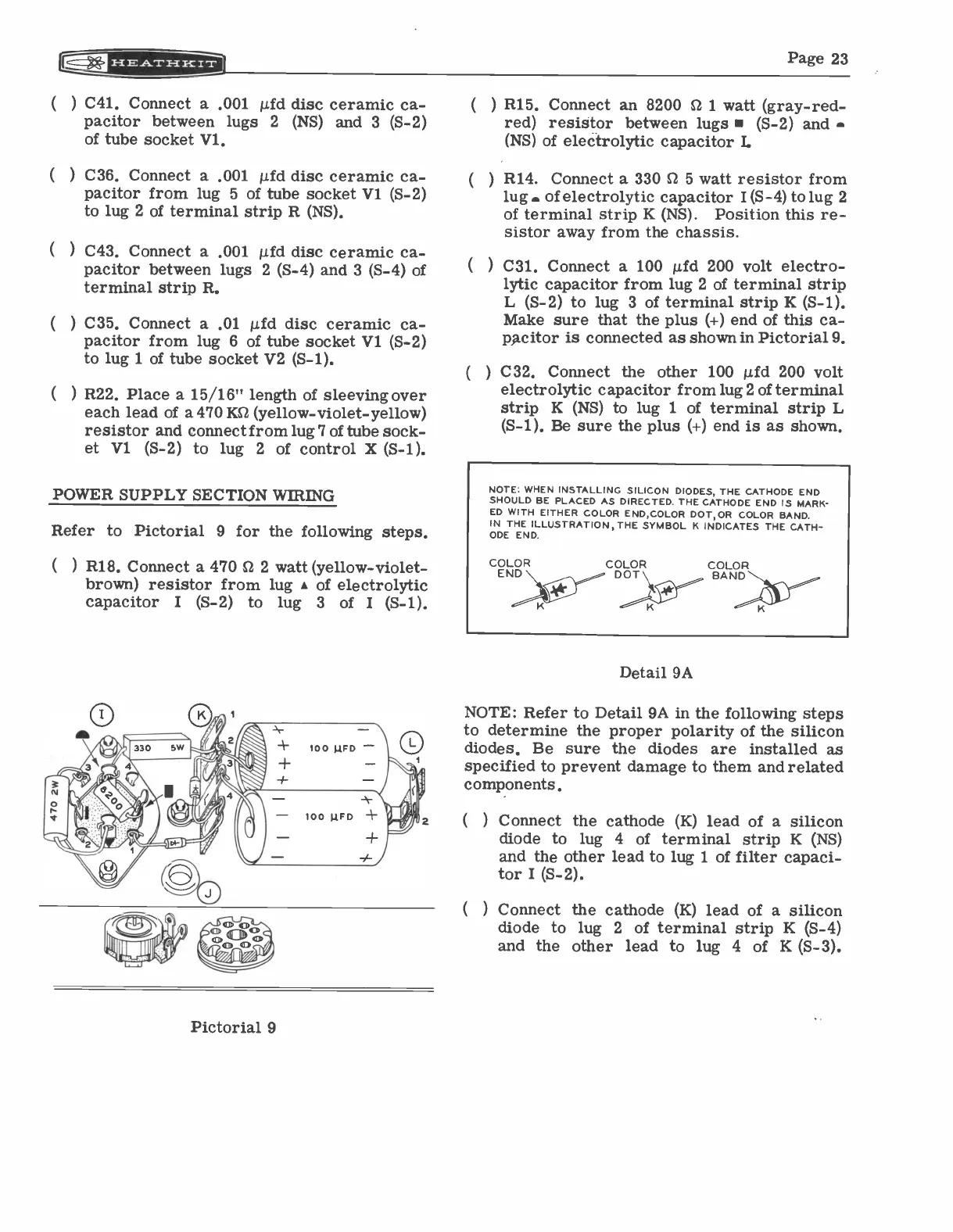
POWER SUPPLY SECTION WIRING
Refer to Pictorial 9 for the following steps.
(
) R18. Connect a 470 S.2 2 watt (yellow -violet
-
brown) resistor from lug
A
of electrolytic
capacitor I
(5-2) to
lug 3 of I
(S-1).
Pictorial 9
(
) R15. Connect an 8200 62 1 watt (gray -red
-
red) resistor between lugs (S-2) and
(NS) of electrolytic capacitor L
(
) R14. Connect a 330 62 5 watt resistor from
lug. of electrolytic capacitor I (S-4) to lug 2
of terminal strip K (NS).
Position this re-
sistor away from the chassis.
(
) C31. Connect a 100 p.fd 200 volt electro-
lytic capacitor from lug 2 of terminal strip
L (S-2) to lug 3 of terminal strip K (S-1).
Make sure that the plus (+) end of this ca-
pacitor is connected as shown in Pictorial 9.
(
) C32. Connect the other 100 p.fd 200 volt
electrolytic capacitor from lug 2 of terminal
strip K (NS) to lug 1 of terminal strip L
(S-1). Be sure the plus (+) end is as shown.
NOTE. WHEN INSTALLING SILICON DIODES, THE CATHODE END
SHOULD BE PLACED AS DIRECTED. THE CATHODE END IS MARK-
ED WITH EITHER COLOR END,COLOR DOT,OR COLOR BAND.
IN THE ILLUSTRATION, THE SYMBOL K INDICATES THE CATH-
ODE END.
COLOR
COLOR
DOT \
BAND
Detail 9A
NOTE: Refer to Detail 9A in the following steps
to determine the proper polarity of the silicon
diodes. Be sure the diodes are installed as
specified to prevent damage to them and related
components.
(
) Connect the cathode (K) lead of a silicon
diode to lug 4 of terminal strip K (NS)
and the other lead to lug 1 of filter capaci-
tor I (S-2).
(
) Connect the cathode (K) lead of a silicon
diode to lug 2 of terminal strip K (S-4)
and the other lead to lug 4 of K (S-3).