Page 22
SOLDER
/HERE
2 3
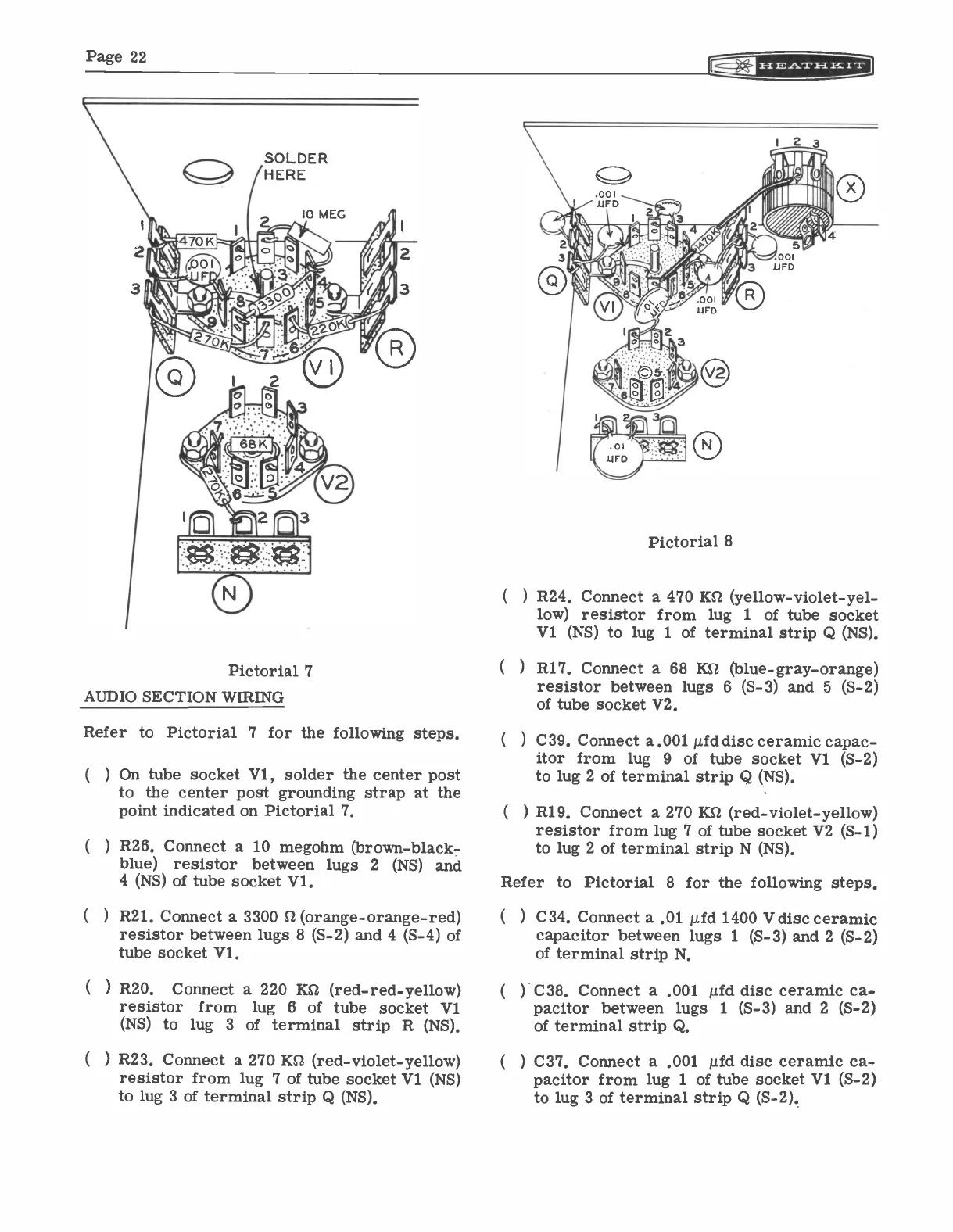
Pictorial 7
AUDIO SECTION WIRING
Refer to Pictorial 7 for the following steps.
) On tube socket V1, solder the center post
to the center post grounding strap at the
point indicated on Pictorial 7.
) R26. Connect a 10 megohm (brown -black
-
blue)
resistor between lugs 2
(NS) and
4 (NS) of tube socket Vl.
)
R21. Connect a 3300 C2 (orange -orange -red)
resistor between lugs 8 (S-2) and 4 (S-4) of
tube socket Vl.
(
) R20.
Connect a 220 KS -2
(red -red -yellow)
resistor from lug 6
of tube socket V1
(NS) to lug
3
of terminal strip R (NS).
) R23. Connect a 270 KO (red -violet -yellow)
resistor from lug 7 of tube socket V1 (NS)
to lug 3 of terminal strip Q (NS).
Pictorial 8
(
) R24. Connect a 470 KIZ (yellow -violet -yel-
low) resistor from lug 1
of tube socket
V1 (NS) to lug 1
of terminal strip Q (NS).
( )
R17. Connect a 68 Kg (blue -gray -orange)
resistor between lugs 6 (S-3) and 5 (S-2)
of tube socket V2.
(
) C39. Connect a.001 µfd disc ceramic capac-
itor from lug 9 of tube socket V1 (S-2)
to lug 2 of terminal strip Q (NS).
(
) R19. Connect a 270 KSZ (red -violet -yellow)
resistor from lug 7 of tube socket V2 (S-1)
to lug 2 of terminal strip N (NS).
Refer to Pictorial 8 for the following steps.
C34. Connect a .01 µfd 1400 V disc ceramic
capacitor between lugs 1
(S-3) and 2 (S-2)
of terminal strip N.
C38. Connect a .001 !Ad disc ceramic ca-
pacitor between lugs
1
(S-3) and 2 (S-2)
of terminal strip Q.
C37. Connect a .001 µfd disc ceramic ca-
pacitor from lug 1 of tube socket V1 (S-2)
to lug 3 of terminal strip Q (S-2).