Page 21
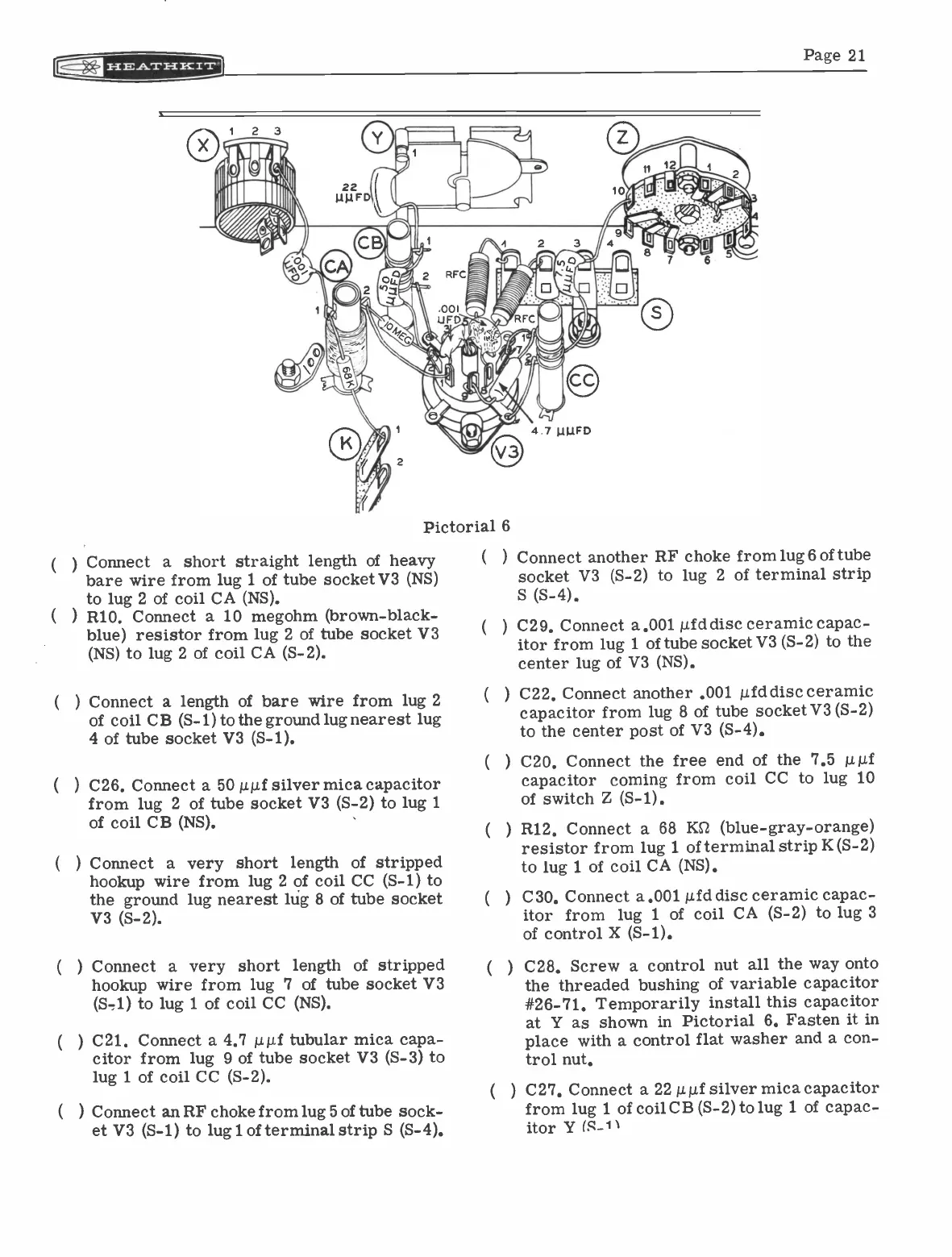
Pictorial 6
Connect a short straight length of heavy
bare wire from lug 1 of tube socket V3 (NS)
to lug 2 of coil CA (NS).
(
) R10. Connect a 10 megohm (brown -black -
blue) resistor from lug 2 of tube socket V3
(NS) to lug 2 of coil CA (S-2).
Connect a length of bare wire from lug 2
of coil CB (S-1) to the ground lug nearest lug
4 of tube socket V3 (S-1).
(
) C26. Connect a 50 illuf silver mica capacitor
from lug 2 of tube socket V3 (S-2) to lug 1
of coil CB (NS).
(
) Connect a very short length of stripped
hookup wire from lug 2 of coil CC (S-1) to
the ground lug nearest lug 8 of tube socket
V3 (S-2).
(
) Connect a very short length of stripped
hookup wire from lug 7 of tube socket V3
(S-1) to lug 1 of coil CC (NS).
(
) C21. Connect a 4.7 litif tubular mica capa-
citor from lug 9 of tube socket V3 (S-3) to
lug 1 of coil CC (S-2).
) Connect an RF choke from lug 5 of tube sock-
et V3 (S-1) to lugl of terminal strip S (S-4).
(
Connect another RF choke from lug 6 of tube
socket V3 (S-2) to lug 2 of terminal strip
S (S-4).
C29. Connect a.001 /Ad disc ceramic capac-
itor from lug 1 of tube socket V3 (S-2) to the
center lug of V3 (NS).
C22. Connect another .001 p.fd disc ceramic
capacitor from lug 8 of tube socket V3 (S-2)
to the center post of V3 (S-4).
C20. Connect the free end of the 7.5 mif
capacitor coming from coil CC to lug 10
of switch Z (S-1).
R12. Connect a 68 KSZ (blue -gray -orange)
resistor from lug 1 of terminal strip K (S-2)
to lug 1 of coil CA (NS).
C30. Connect a.001 p.fd disc ceramic capac-
itor from lug 1 of coil CA (S-2) to lug 3
of control X (S-1).
) C28. Screw a control nut all the way onto
the threaded bushing of variable capacitor
#26-71. Temporarily install this capacitor
at Y as shown in Pictorial 6. Fasten it in
place with a control flat washer and a con-
trol nut.
) C27. Connect a 22 µµf silver mica capacitor
from lug 1 of coil CB (S-2) to lug 1 of capac-
itor Y (S_11