Page 30
3- CONDUCTOR
CABLE
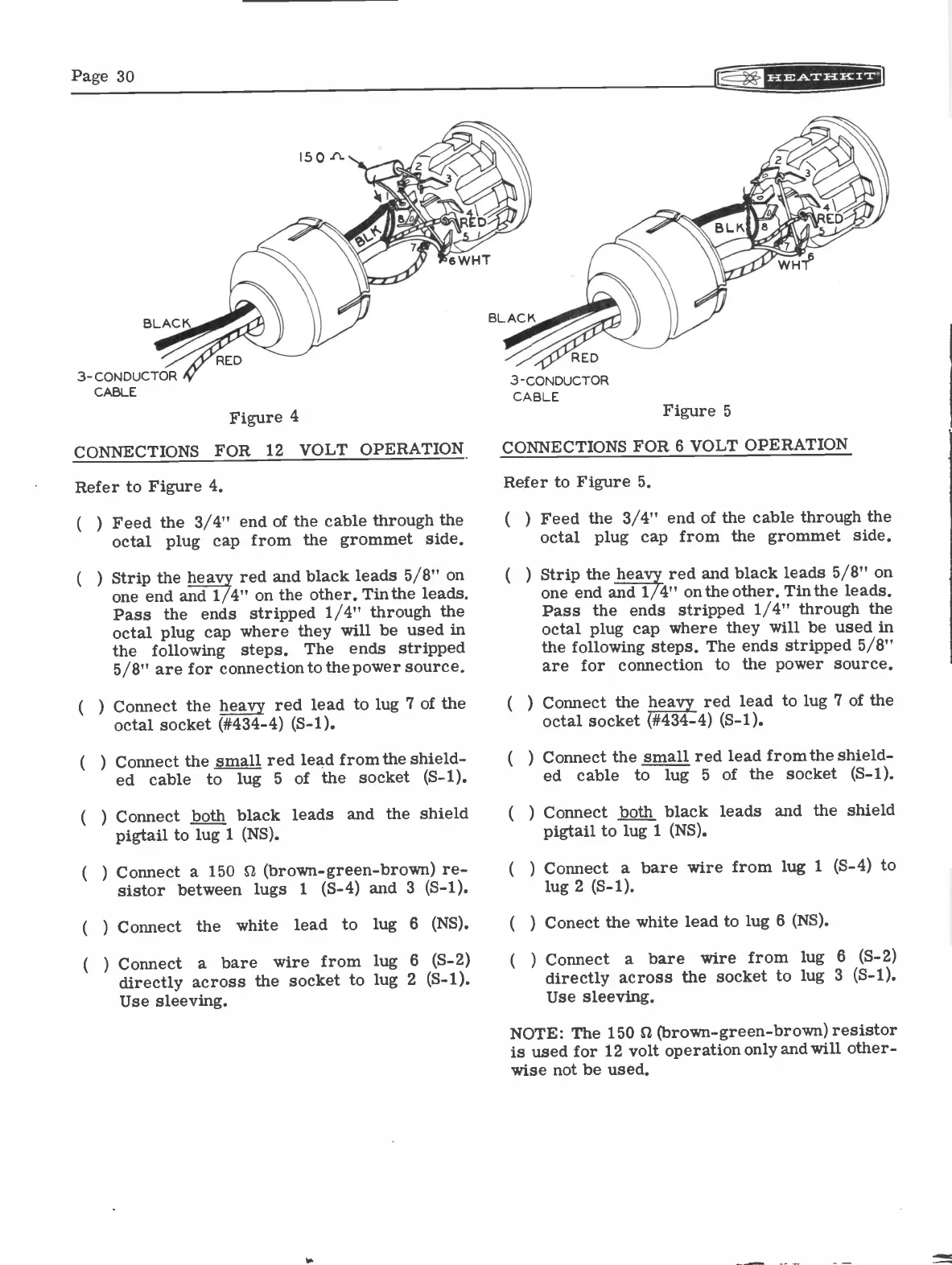
Figure 4
CONNECTIONS FOR 12 VOLT OPERATION
Refer to Figure 4.
( )
Feed the 3/4" end of the cable through the
octal plug cap from the grommet side.
Strip the heavy red and black leads
5/8"
on
one end and 1/4" on the other. Tin the
leads.
Pass the ends stripped 1/4" through the
octal plug cap where they will be used in
the
following
steps.
The ends stripped
5/8"
are for connection to the power source.
Connect the heavy red lead to lug 7 of the
octal socket (#434-4) (S-1).
Connect the small red lead from the shield-
ed cable
to lug
5
of the socket (S-1).
Connect both black leads and the shield
pigtail to lug 1 (NS).
3 -CONDUCTOR
CABLE
Figure
5
CONNECTIONS FOR 6 VOLT OPERATION
Refer to Figure 5.
(
)
( )
Feed the 3/4" end of the cable through the
octal plug cap from the grommet side.
Strip the heavy red and black leads
5/8"
on
one end and 1/4" onthe other. Tin the leads.
Pass the ends stripped 1/4"
through
the
octal plug cap where they will be used in
the following steps. The ends stripped
5/8"
are for connection to the power source.
Connect the heavy red lead to lug 7 of the
octal socket (#434-4) (S-1).
Connect the small red lead from the shield-
ed
cable
to
lug
5
of the socket (S-1).
Connect both black leads and the shield
pigtail to lug 1 (NS).
(
) Connect a
150
SZ (brown -green -brown) re-
sistor between lugs
1
(S-4) and 3 (S-1).
(
) Connect a bare wire from lug 1 (S-4) to
lug 2 (S-1).
(
) Connect the
white
lead
to
lug 6
(NS).
(
) Conect the white lead to lug 6 (NS).
(
) Connect a bare wire from lug
6 (S-2)
(
) Connect a bare wire from lug 6
(S-2)
directly across the socket to lug 2
(S-1).
directly across the socket to lug 3
(S-1).
Use sleeving.
Use sleeving.
NOTE: The
150
S2 (brown -green -brown) resistor
is used for 12 volt operation only and will other-
wise not be used.